logo

Circuit Function and Diagrams for a Two-Player Game with LED Output


Added on  2023-04-23

7 Pages703 Words163 Views
 | 
 | 
 | 
Name:
Student Number:
E-Mail Address:
Circuit Function and Diagrams for a Two-Player Game with LED Output_1

Circuit Function:
Part A:
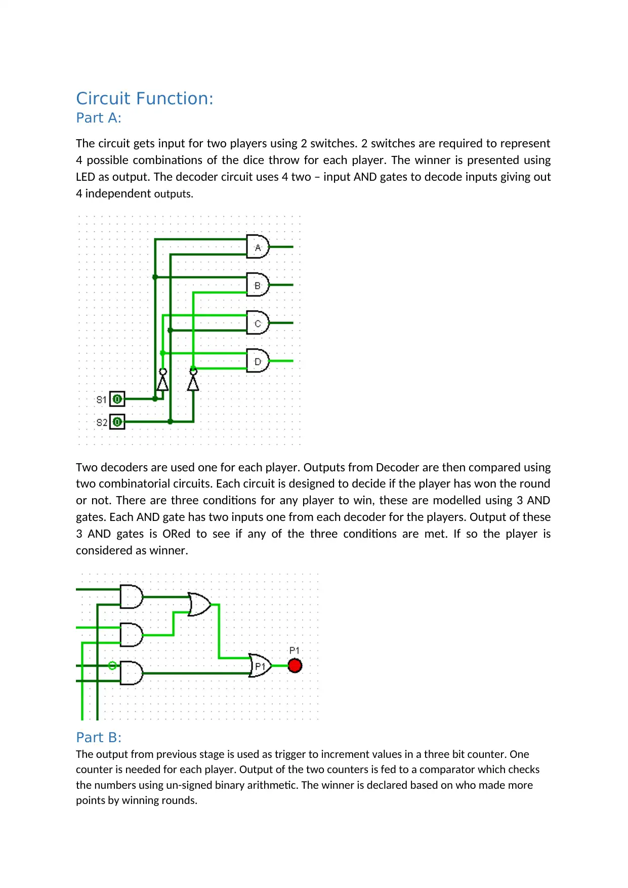
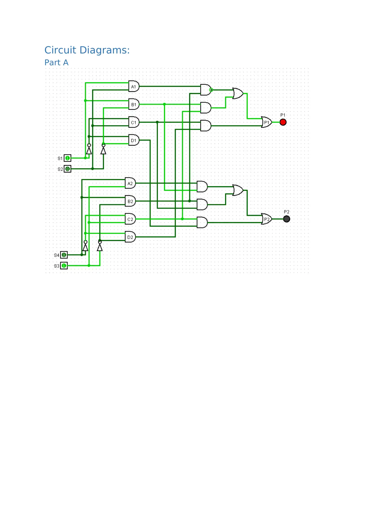
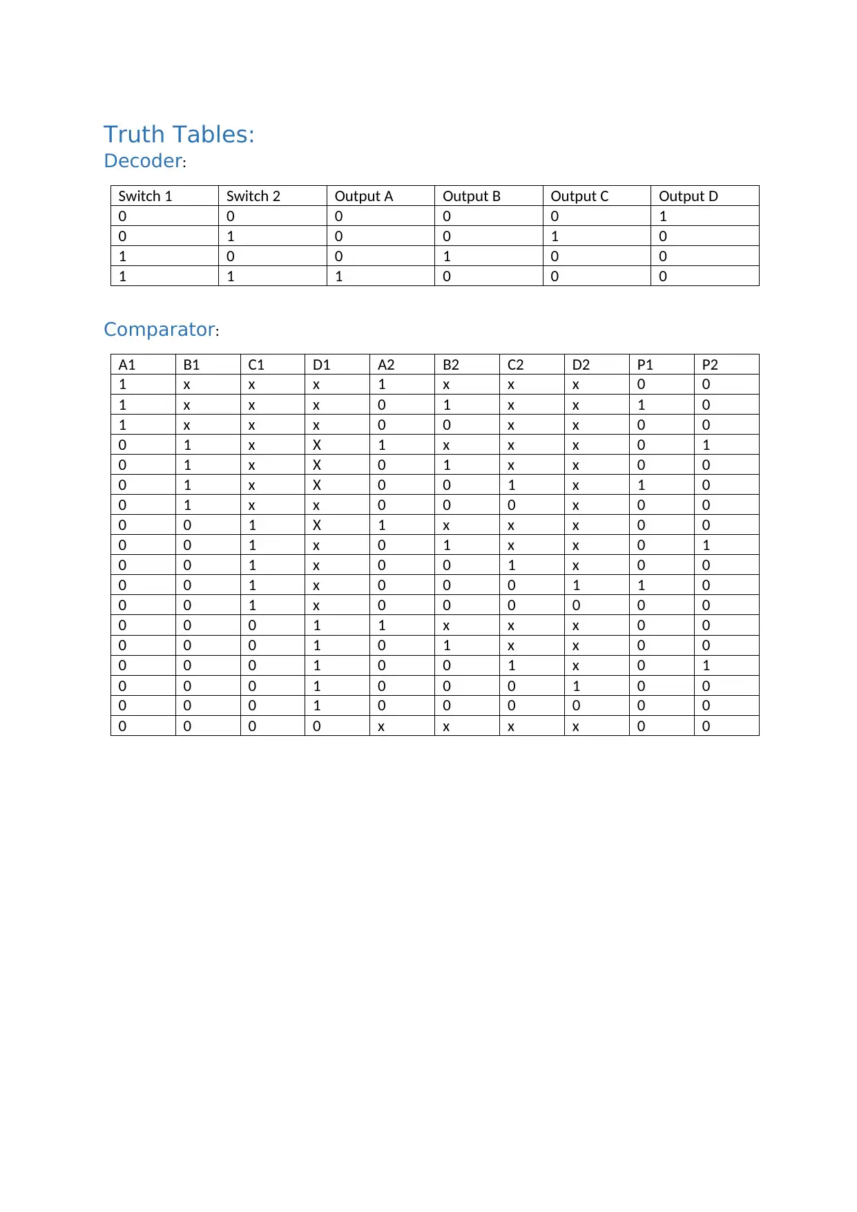
The circuit gets input for two players using 2 switches. 2 switches are required to represent
4 possible combinations of the dice throw for each player. The winner is presented using
LED as output. The decoder circuit uses 4 two – input AND gates to decode inputs giving out
4 independent outputs.
Two decoders are used one for each player. Outputs from Decoder are then compared using
two combinatorial circuits. Each circuit is designed to decide if the player has won the round
or not. There are three conditions for any player to win, these are modelled using 3 AND
gates. Each AND gate has two inputs one from each decoder for the players. Output of these
3 AND gates is ORed to see if any of the three conditions are met. If so the player is
considered as winner.
Part B:
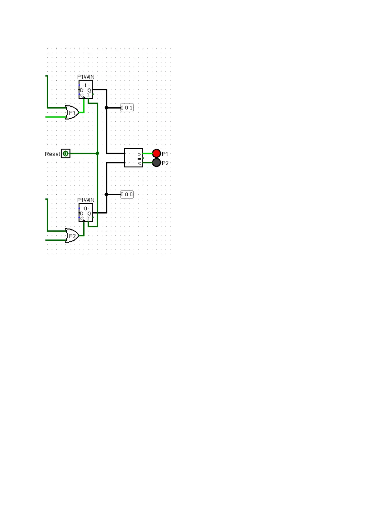
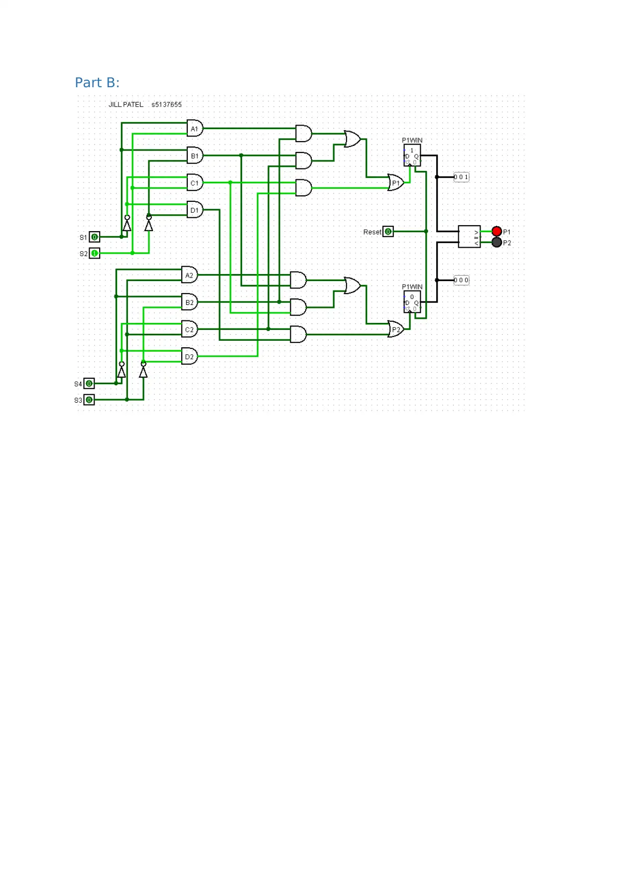
The output from previous stage is used as trigger to increment values in a three bit counter. One
counter is needed for each player. Output of the two counters is fed to a comparator which checks
the numbers using un-signed binary arithmetic. The winner is declared based on who made more
points by winning rounds.
Circuit Function and Diagrams for a Two-Player Game with LED Output_2

Circuit Function and Diagrams for a Two-Player Game with LED Output_3

End of preview

Want to access all the pages? Upload your documents or become a member.

Related Documents
Circuit Function: Decoder and Comparator for Lift Movement
|6
|1194
|63

Understanding 7-Segment Display Decoders
|10
|1601
|26

DIGITAL LOGIC QUESTION ONE 4 BIT ADDER-SUBTRACTOR
|10
|942
|259

Machine Circuit Design Assignment Project
|5
|963
|26

Identifying Properties of a Synchronous Counter
|5
|747
|249

State Diagram:.
|13
|839
|100