logo

Identifying Properties of a Synchronous Counter

5 Pages747 Words249 Views
   

Added on  2023-04-24

About This Document

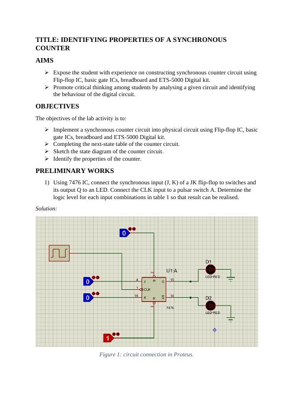
The lab activity aims to expose students to constructing synchronous counter circuit using Flip-flop IC, basic gate ICs, breadboard and ETS-5000 Digital kit. The lab activity also promotes critical thinking among students by analysing a given circuit and identifying the behaviour of the digital circuit. The lab activity includes preliminary works, lab activities and questions. The lab activity solutions are provided in the document.

Identifying Properties of a Synchronous Counter

   Added on 2023-04-24

ShareRelated Documents
STUDENT’S NAME:
PROFESSOR’S NAME:
TITLE: IDENTIFYING PROPERTIES OF A SYNCHRONOUS
COUNTER
DATE DUE:
SIGNATURE:
Identifying Properties of a Synchronous Counter_1
TITLE: IDENTIFYING PROPERTIES OF A SYNCHRONOUS
COUNTER
AIMS
Expose the student with experience on constructing synchronous counter circuit using
Flip-flop IC, basic gate ICs, breadboard and ETS-5000 Digital kit.
Promote critical thinking among students by analysing a given circuit and identifying
the behaviour of the digital circuit.
OBJECTIVES
The objectives of the lab activity is to:
Implement a synchronous counter circuit into physical circuit using Flip-flop IC, basic
gate ICs, breadboard and ETS-5000 Digital kit.
Completing the next-state table of the counter circuit.
Sketch the state diagram of the counter circuit.
Identify the properties of the counter.
PRELIMINARY WORKS
1) Using 7476 IC, connect the synchronous input (J, K) of a JK flip-flop to switches and
its output Q to an LED. Connect the CLK input to a pulsar switch A. Determine the
logic level for each input combinations in table 1 so that result can be realised.
Solution:
Figure 1: circuit connection in Proteus.
Identifying Properties of a Synchronous Counter_2

End of preview

Want to access all the pages? Upload your documents or become a member.

Related Documents
Desklib Online Library for Study Material with Solved Assignments
|12
|2074
|254

Digital Logic Circuit and Digital Components | Assignment
|10
|899
|31

Computer Architecture and Organization I CMPE 263
|12
|1578
|375

State Diagram:.
|13
|839
|100

Power Supply Circuit
|4
|525
|20

Assignment On State Machine Positive Edge Triggered
|2
|1003
|421