Sorting Network and ADT Implementation
VerifiedAdded on 2019/09/24
|13
|6840
|207
Essay
AI Summary
The assignment aims to test students' ability to sort a given network in a breadth-first fashion and create an Orderly Binary Decision Diagram (OBDD) computation. The provided code must be used without modification, and the cover sheet must be included with the submission. The assignment is designed to promote good design decisions, testing, and following specifications carefully.
Contribute Materials
Your contribution can guide someone’s learning journey. Share your
documents today.

Data Structures and Algorithms
Assignment
Semester 2, 2016
Department of Computing
Curtin University
1 Preamble
In practicals you have implemented and learned about a number of algorithms and ADTs and will be
implementing more of these in the remaining practicals. In this assignment, you will be making use
of this knowledge to implement a system that is somewhat more open ended. In this system, you
will be deciding (for the most part) how to structure the program, how to use the abstract data types
and your program will need to decide on the flow of objects in and out of them. Feel free to re-use
the generic ADTs from your practicals. However, remember to self-cite; if you submit work that you
have already submitted for a previous assessment (in this unit or any other) you have to specifically
state this.
The start of this assignment specification document does look somewhat daunting and confusing. I
recommend that you highlight and/or take notes. Jump to Section 4 for a breakdown of what your
program is expected to do for each set of marks. Note that, as you can see from Section 4, you can
get many of the marks for properly completing your practicals properly and then doing a small
amount of work to apply that to this assignment.
1.1 Requirements for passing the unit
Please note: As specified in the unit outline, it is necessary to have attempted the assignment in
order to pass the unit. As a guide, you should score at least 15% to be considered to have attempted
this assignment. We have given you the exact mark breakdown in Section 4.2. Note that the marks
indicated in this section represent maximums, achieved only if you completely satisfy the
requirements of the relevant section.
Plagiarism is a serious offence. This assignment has many correct solutions so plagiarism will be easy
for us to detect (and we will). For information about plagiarism, please refer to
http://academicintegrity.curtin.edu.au.
In the case of doubt, you may be asked to explain your code and the reason for choices that you
have made as part of coding to the unit coordinator. A failure to adequately display knowledge
required to have produced the code will most likely result in being formally accused of cheating.
Finally, be sure to secure your code. If someone else gets access to your code for any reason
(including because you left it on a lab machine, lost a USB drive containing the code or put it on a
public repository) you will be held partially responsible for any plagiarism that results.
Secure Best Marks with AI Grader
Need help grading? Try our AI Grader for instant feedback on your assignments.

1.2 Late Submission
I know for the vast majority of you, I don’t need to tell you what is in this section. But every
semester, someone always tries to see what they can get away with here. For the benefit of fairness
to the vast majority of you who do the right thing, we need to make the rules surrounding late
submission clear
As specified in the unit outline, you must submit the assignment on the due date. Acceptance of late
submissions is not automatic and will require supporting documentation proving that the late
submission was due to unexpected factors outside your control. See the unit outline for details as to
the procedure for requesting that an assessment be accepted after the due date.
Note that external pre-scheduled commitments including, but not limited to, work, travel, scheduled
medical, sporting, family or community engagements are not considered unexpected factors outside
your control. If you know you have, or are likely to have, such engagements and that they may affect
your ability to complete the assignment, you will be expected to have planned your work
accordingly. This may mean that you need to start and/or complete your assignment early to make
sure that you are able to hand it in on time.
Also note that IT related issues are almost never a valid excuse. These include computer crashes,
hard disk corruption, viruses, losing computers/storage media, networks going down (even if it is
Curtin’s network - outages of the entire Curtin network of more than 24 hours may be considered
depending on circumstances) or the like. As IT professionals in training, you are expected to have
suitable backups and alternative ways of getting your assignment completed in the event that any IT
problems are encountered. You are also expected to submit your assignment ahead of time to allow
for unforeseen issues.
In the event that you submit your assignment late and are deemed to have a valid excuse, you will
be penalised 10% (that is, 10% out of 100%, not out of what you would have received) per calendar
day that you are late, up to a maximum of seven (7) calendar days. Any work submitted after this
time will not be marked and you will automatically fail the unit. Note that if you are granted an
extension you will be able to submit your work up to the extended time without penalty – this is
different from submitting late.
Note that the requirements for passing this unit are applied after penalties. An assignment normally
scoring 20% that is submitted one day late, even with a valid excuse, will score only 10% and thus
not satisfy the requirements for passing this unit.
1.3 Clarifications and Amendments
This assignment specification may be clarified and/or amended at any time. Such clarifications and
amendments will be announced in the lecture and on the unit’s Blackboard page (not necessarily at
the same time and not necessarily in that order). These clarifications and amendments form part of
the assignment specification and may include things that affect mark allocations or specific tasks. It
is your responsibility to be aware of these, either by attending the lectures, watching the iLecture
and/or monitoring the Blackboard page.
Note that there will be at least one minor amendment to these requirements. In a normal real-world
project a large number of amendments and clarifications would be made, so marking at least one

minor amendment is helpful in teaching you to adjust. The planned amendment(s) will not require a
large amount of time assuming you have made sensible decisions.
2 The Problem
Your assignment will address the problem of computing the reliability of a network. In particular,
you will compute the two-terminal reliability of a directed network. This is surprisingly hard to do; all
existing solutions have an exponential worst-case complexity. Compare this with the algorithms that
have been covered so far that generally have quadratic complexity at worst. For comparison, a
quadratic with input 100 (in other words we computer 1002=10,000) isn’t very large, but even a
small exponential function with input 100 is huge (2100 has about 30 digits). In other word it’s hard to
compute the two-terminal reliability of even a network with only 100 devices. In this assignment you
will be computing the reliability of networks with thousands of devices.
The first part of the problem is to read the network in from a provided file. These files are discussed
in Appendix II. Once this is done, the data may need to be sorted as specified in Appendix I and the
specifications for the Network class in Section 3.4.
The second part of the problem is to process the network, one vertex at a time, to compute the
reliability value. The main algorithm in the OBDDH class will be provided to you, as will the details of
HNode creation and modification which make up the most challenging parts of the algorithm. The
details of both of these classes can be found in Section 3. The OBDDH class represents the main
decision diagram used to compute the reliability and each node of that diagram is a HNode object.
Your job is to provide the support classes that will allow this to function. This simulates working in a
team with an expert in the area who will supply the algorithm-specific code while you provide the
production code.
As part of the teamwork simulation, you are required to write code for a number of classes and
other code will be provided for you. This is specified in Section 3. The code provided will be released
in parts, to simulate your team member’s progress on their work. This means that you’ll have to do
coding on your sections without being able to test how your code fits in with the provided code. The
only way to do this is for both parties to stick to specifications exactly and to carefully unit test their
code.
3 Class Specifications
This section contains the specifications of the main classes required in this assignment. Some of the
code for this will be given to you over time (this represents code created by other members of your
programming team). All code given to you will adhere to the specifications in this section, meaning
you have to be careful that your code does as well or you will not be able to fit the various pieces of
code together. You may not change any part of the code given to you.
In order to implement the classes that are your responsibility, you may need to create other classes.
Decisions such as this (and all main decisions) must be documented – see Section 4.1. You will be
marked not just on having working code but also on the efficiency of the overall solution (part of
which is making good decisions) and the quality of your code.

Each class lists the methods that will be provided and those that you are required to write. Provided
methods will be made available over time and required methods are ones that will be utilized by the
provided methods; you must code required methods to exactly match the specifications or they will
not work with the provided code. You may also need to code other methods that are not listed in
order to use the classes yourself. Your implementation of all classes listed below must be named
exactly as specified.
Note that while the classes must implement the required methods, it is acceptable for these to be
inherited from a parent class where appropriate. In other words the calls to those methods must
function but the actual code can be elsewhere, at your discretion. When to use inheritance is an
important part of OO programming, and you should identify this in your documentation (see Section
4.1).
You must write the classes yourself. You may not use existing Java classes for any class listed below.
3.1 FloatingPoint
This ADT is responsible for safe handling of floating point numbers. This class should have a static
class variable precision that is of type double. This should be set to 0.00000001 by default.
Provided: None
Required:
public FloatingPoint( double value) – constructor that sets the initial contents of the
FloatingPoint to the double value
public FloatingPoint( FloatingPoint num) – copy constructor
public boolean equals( FloatingPoint num ) - checks to see whether the two numbers are
within precision of each other.
public static void setPrecision( double value ) – sets the precision to the new value.
public void add( FloatingPoint num ) – adds the given FloatingPoint number to the current
one. So calling a.add( b ) will result in a containing the sum of a and b.
public void add( int num ) – adds the given integer to the current FloatingPoint one. So
calling a.add( b ) will result in a containing the sum of a and b.
public void invert() – inverts the floating point number using probability laws by subtracting
it from 1. So calling a.invert( ) will result in a containing the result of 1.0 - a.
public void multiply( FloatingPoint num ) – multiplies the given FloatingPoint number into
the current one. So calling a.multiply( b ) will result in the object a containing the product of
the values previously stored in objects a and b. The value in object b should not be changed.
public String toString() – returns the floating point number stored in the class as a String
3.2 Vertex
This ADT is responsible for storing the devices of the network as vertices in the graph. Vertices must
store all of the information related to them from the network file (see Appendix II).
Devices must have one of the following device types: RV325, 2291K9, 1841
Provided: None
Paraphrase This Document
Need a fresh take? Get an instant paraphrase of this document with our AI Paraphraser
Required:
public FloatingPoint getRel() – returns the reliability value stored in the vertex as a member
of the FloatingPoint class.
public boolean isSource() – true if the vertex is the source vertex (as defined in the file
specifications in Appendix II)
public boolean isTarget() – true if the vertex is the target vertex (as defined in the file
specifications in Appendix II)
public String getName() – returns the name of the device
public String getType() – returns the type of the device
public String toString() – convert the Vertex into a String for display.
3.3 Edge
This ADT is responsible for storing the communications of the network as edges in the graph. Edges
must store all of the information related to them from the network file (see Appendix II).
Edges must have one of the following types: CAT4, CAT5, Wireless, Satellite
Provided: None
Required:
public FloatingPoint getRel () – returns the reliability value stored in the vertexedge as a
member of the FloatingPoint class.
public String getName() – returns the name of the device
public String getType() – returns the type of the device
public Vertex getFrom(),public Vertex getTo() – get the endpoints of the edge.
public boolean isDirected() – returns true if the edge is directed and false if it is undirected.
public String toString() – convert the Edge to a String for display.
3.4 Network
This class is the ADT responsible for managing the network to be analysed. A network contains
vertices and edges, which must be stored in the same order as read in from a sorted file (with
suffix .srt) or otherwise they must be sorted before being used.
Provided: None
Required:
public Network() – empty constructor.
public Vertex nextVertex() – returns the next vertex stored in the network. This is used to
traverse the vertices one at a time, in the order that results from the sorting. The first time
this method is called the first (source) vertex should be returned, and when no more vertices
are available a null should be returned.
public Vertex[] adjacent( Vertex v ) – returns all vertices adjacent to the current vertex. A
vertex w is adjacent to vertex v if an edge exists that has v as the from vertex and w as the to
vertex.

public Edge[] adjacentE( Vertex v ) - as above, but returns all of the edges adjacent to v
instead of the vertices. An edge is adjacent to v if it has v as an endpoint (either to or from).
The size of the array should be correct (ie if there are three adjacent edges then the array
returned has size 3).
public Network( String filename ) – a constructor that accepts the file name and reads the
contents of the network in from a network file (see the specification in Appendix II). Throws
appropriate IO exceptions. If the network file ends with the .srt suffix, it is assumed to be
already sorted. If this is not the case (it should end in a .nt suffix) then it should be sorted
using the sort() method below and then saved. The filename in this case is identical but
the .nt suffix will be replaced by a .srt suffix. In other words, if you load the file “file.nt” the
fact that it’s unsorted should be detected, the network should be sorted, and the sorted
network should be written to the file “file.srt”. Sorting is described in Appendix I.
public void display() – write the network to the screen in a sensible fashion.
private void sort() – sort the network. Vertices must be sorted in increasing distance from
the source vertex and edges must be sorted in increasing order for the lower of the two
endpoints and then the upper endpoint. See Appendix I for details on vertex sorting.
3.5 HNode
This is a node of the hybrid decision diagram. It has a private class variable FloatingPoint reliability
that stores the reliability associated with the network state represented by the node. It also has a
private class variable state that stores the state the node represents.
Provided:
public HNode() – the default constructor creates the root node of the OBDDH diagram
public boolean isEqual( HNode node ) – returns true if the given node is equal (isomorphic)
to the current node.
public void mergeInto( HNode node ) – merges the current node into the provided node. The
current node should not be used further after this.
public HNode makePos( Vertex v, Edge elist[] ) – creates a new node that is the positive child
of the current one.
public void makeNeg( Edge Vertex e v ) – turns the current node into its own negative child.
This is done as an optimization since the node would otherwise be discarded after the
negative child was created.
public boolean isSuccess() – returns true only if the node is successful. A node is considered
successful if it represents a state where the source is connected to the target.
public boolean isFailed() – returns true only if the node is failed. A node is considered failed
if it represents a state of the network where the source is unable to connect to the target.
public FloatingPoint getRel() – returns the reliability of the node
public int getCode() – returns an integer that represents the state of the node, in case a hash
table is to be used
3.6 Qc
This class was implemented as a circular queue in the initial version of the OBDDH, and its name
refers to the fact it was the queue storing HNodes at the current level of the OBDDH – the level now

being processed. You should implement it in the most efficient way, which is not necessarily a
circular queue. The actual order of the nodes in Qc isn’t particularly important
Provided: None
Required:
public Qc( HNode root ) – initializes the structure to be empty apart from the given root
node.
public HNode front() – removes the first node in the structure and returns it.
public boolean isEmpty() – returns true if no nodes remain stored, or false otherwise.
public void insert( HNode node ) – inserts the given node to the back of the structure
3.7 Qn
This class was implemented as a circular queue in the initial version of the OBDDH, and its name
refers to the fact that it was the queue storing HNodes at the next level of the OBDDH, one level
below the level currently being processed. HNodes are added to Qn one at a time, and only if there
isn’t an equal node already present. They are removed all at once and moved to Qc by the swap
method.
Provided: None
Required:
public Qn() – initialized the structure to be empty
public boolean isEmpty() – returns true if no nodes remain stored, or false otherwise
public int numNodes() – returns the number of nodes currently stored in the structure
public boolean add( HNode node ) – checks to see if a node equal to the provided node is
already stored in the structure. If an equal node is found the provided node is merged into
the existing one. If no equal node is found the provided node is stored. It is imperative that
this method be as efficient as possible. This means that deciding whether or not a duplicate
node exists must be efficient. This method returns true if an existing node was found or false
otherwise.
public void swap( Qc current ) – moves all of the nodes stored in this structure and adds
them to current, one at a time. This is used when a level of the diagram has been finished
and the algorithm is about to start processing the next level. When this method has
completed this structure should be empty and all nodes that were in this structure should be
in current.
3.8 OBDDH
This stores the main diagram and computes the reliability of the network. The main class definition
will be provided. It includes a class variable Network net that stores the network to be analysed. It
also has two private class variables that store HNodes – private Qn next and private Qc current.
Provided:
public OBDDH( String filename ) – default constructor that creates the initial, empty diagram
and then loads up the network and computes the network’s reliability
Secure Best Marks with AI Grader
Need help grading? Try our AI Grader for instant feedback on your assignments.
private void compute() – computes the reliability of the network, which must have been
initialized before this is called
public void displayRel() – displays the reliability of the network to the screen
Required:
private void loadNetwork( String filename ) – initializes the network by calling the
constructor to load information from a file
private void addToQn( HNode node ) – after a new child node has been created this method
attempts to add it to next.
4 Submission
Submit electronically via Blackboard. As per the preamble, make sure to submit early. In fact I
strongly encourage you to submit multiple times – I will only mark the last attempt. Take care not to
submit your last version late though. Read the submission instructions very carefully.
You should submit a single file, which should be zipped (.zip) or tarred (.tar.gz). Check that you can
decompress it on saeshell01p.curtin.edu.au. This is also the computer on which your work will be
tested, so make sure that your work runs there. The file must be named DSA_Assignment_<id>
where the <id> is replaced by your student id. There should be no spaces in the file name; use
underscores as shown.
The file must contain the following:
Your code. This means all .java files needed to run your program. Do not include any .class
files. Do include code provided to you as part of the assignment if that is required to run
your program.
Your test harnesses. One of the easiest ways for us to be sure that your code works is to
make sure that you’ve tested it properly. Our test harnesses may not work for some of your
classes and you may have classes that we’re not specifically asking for, so make it easy for us
to test your work. You do not have to provide a test harness for any code that is provided to
you (such as most of HNode and its associated class) but you may want to write one anyway
to make sure that you understand how the code is behaving. A test harness for class X
should be called UnitTestX. For example the test harness for Vertex should be named
UnitTestVertex.
Documentation for your code, as described in Section 4.1.
A signed and dated cover sheet. These are available from the [[Computing Colloquium]]
Blackboard unit or from the Computing reception (building 314, 3rd floor). You can sign a
hard copy and scan it in or you can fill in a soft copy and digitally sign it.
You may include a Makefile, but this is not required. We will use javac *.java to compile your
files and run the unit tests by their expected names.
Do not include any directories – in other words add files directly to the archive rather than
compressing an entire directory. When your submission is expanded, we want to be able to
use javac in the current directory. We will be using scripts for some of the testing and don’t
want the scripts failing because your code is not where we expect it to be. If we decompress
your submission it should create a number of files in the directory we ran the

decompression in – if this isn’t the case you could get zero marks for the script-based
marking, so check your submission before uploading it.
Do not include .class files or anything else that we do not need. We will compile your .java
files to ensure that what we’re testing is what we’re reading.
Make sure that your file contains what is required. Anything not included in your submission will not
be marked, even if you attempt to provide it later. It is your responsibility to make sure that your
submission is complete and correct.
4.1 Documentation
You need to submit documentation in docx or pdf format. Your documentation should include the
following:
An overview of your code, explaining any questions that the marker may have. This is
supplemented by the comments in your code. In general, if the marker is looking at your
code and isn’t sure why you have done something in that particular way, they will check
your documentation to see if they can find an explanation. Using an automated
documentation system like Javadocs may be very helpful. It is not required, though.
A description of any classes you have, other than those covered in the class specification
section. If you have additional classes then you need to let us know not only what the
purpose of that class is but why you chose to create it. As part of this, also identify and
justify any places where it was possibly useful to create a new class but you chose not to,
especially when it comes to inheritance.
Justification of all major decisions made. In particular, when you choose an ADT, underlying
data structure or an algorithm, you need to justify why you chose that one and not one of
the alternatives. These decisions are going to be of extreme importance in this assignment.
4.2 Marking
Marks will be awarded to your submission as follows:
[40 marks] Decisions made. This is mainly things like choosing the right class breakdown,
ADT, underlying data structure and algorithm. Note that you will only get these marks if you
adequately justify your decisions and properly implement them. So, for example, if you
choose a sorting algorithm and adequately justify it but aren’t actually able to implement it
you’ll only get part of the marks. Any justification should be presented in the
documentation, which means that your documentation is worth 40% of your marks for this
assignment. Start documenting early.
[20 marks] Code testing. We’ll have a number of tests to run, and you get marks
proportional to how many tests your code passes. If your code passes all of the tests, then
you will get all of these 20 marks. This will involve loading a network and computing the
reliability. Note that these tests will be script based, so if you have something set up in a way
that breaks specifications so that the script doesn’t work, you won’t get those marks. Some
of the tests will be based on the efficiency of your implementation, so a naïve
implementation that doesn’t use optimal structures and algorithms may not be able to
complete the tests in a reasonable amount of time.

[15 marks] Implementation of the Network and associated classes. This includes Vertex,
Edge and any other classes you create as part of this. It also includes implementing all
required methods associated with these classes. We will use unit testing as well as looking at
code quality; your test harnesses will have a big impact on these marks.
[25 marks] Implementation of the OBDDH and associated classes not relating to the
Network. It also includes HNode, Qc, Qn and any other classes that you have created to
support them, as well as all required methods for these classes. We will use unit testing as
well as looking at code quality; your test harnesses will have a big impact on these marks.
Marks will be deducted for not following specifications outlined in this document, which
includes incorrect submission format and content and using built-in Java ADTs.
Marks will be deducted for changing or not using provided code.
If the cover sheet isn’t provided with your submission, your submission will not be marked
and you will be awarded zero (0) marks. If you forget to submit the cover sheet you will be
allowed to submit it separately to the unit coordinator (by e-mail or in person) but will lose 5
marks.
The aims of this marks breakdown is as follows:
To reward you for good design decisions, but not unless you’re able to implement them. This
is the core aim of the unit.
To let you score some marks if you get the program working but make with poor decisions. If
all of your decisions are based only on ease of implementation you can still score the 40
marks from the two implementation categories and will score most of the marks from
testing (around 15 to 17), meaning you can pass if all of your code works perfectly and is of
sufficient quality. It’s taking a risk, though.
To promote good testing. Industry is repeatedly telling us they are really looking for students
who can properly test their code.
To teach you to follow specifications carefully. If you name your files incorrectly you can lose
large amounts of marks form our tests failing. You also need to meet the exact requirements
for class and method templates, and so on. Follow the specifications in this document
carefully.
To reward students who have been serious about doing their practical sheets.
Appendix I: Example of Network Sorting
It is generally believed by reliability researchers that sorting the network in a breadth-first fashion
increases the efficiency of the OBDD computation. For this reason, the network read in needs to be
sorted appropriately. We sort vertices in increasing order from the source and the edges in
increasing order of first the smaller endpoint and then the larger.
Consider the simple network below. The vertices are numbered from 0 to 3 and the edges from 0 to
4; vertex 0 is the source and vertex 3 is the target. A correct ordering of the vertices would be 0,1,2,3
but 0,2,1,3 would also be correct since both vertices 1 and 2 are one edge away from the source and
can thus be in any order, but vertex 0 is the source (distance zero) and vertex 3 is two edges away
and must thus be last.
Paraphrase This Document
Need a fresh take? Get an instant paraphrase of this document with our AI Paraphraser

The edges for the network are e0 = (0,1), e1 = (0,2), e2 = (1,2), e3 = (1,3) and e4 = (2,3). These are in the
correct order given the first ordering of the vertices. If we had put vertex 2 ahead of vertex 1 then
we would need to switch the order of e0 and e1, as well as the order of e3 and e4.
As an additional example, consider the network above. If the source is vertex 0 (I’ll use v0 to denote
this) then the vertices at distance 1 are v1, v2 and v3, the vertices at distance 2 are v4, v5 and v6,
those at distance 3 are v7 and v8 and the only vertex at distance 4 is v9. The distance in each case is
the smallest number of steps (also called hops) from the source to that vertex. You can get to v4
through v1 in two hops, so the distance is two despite also being able to reach it through longer
paths (for example via v3, v6 and then v5).
This means that the following are some of the many valid sortings of the vertices:
v0, v1, v2, v3, v4, v5,v6, v7, v8, v9
v0,v3, v1, v2, v5, v6, v4, v8, v7, v9
As can be seen, v0 has to be first since it’s the source, and thus the only vertex at distance zero. The
three distance 1 vertices come next, in any order, followed by the three distance 2 vertices, also in
any order. Finally we have the two distance 3 vertices (in any order) and the only distance 4 vertex
must be last. Thus there are many possible “correct” sortings.
1
0
03
3
2
1 2
4
3
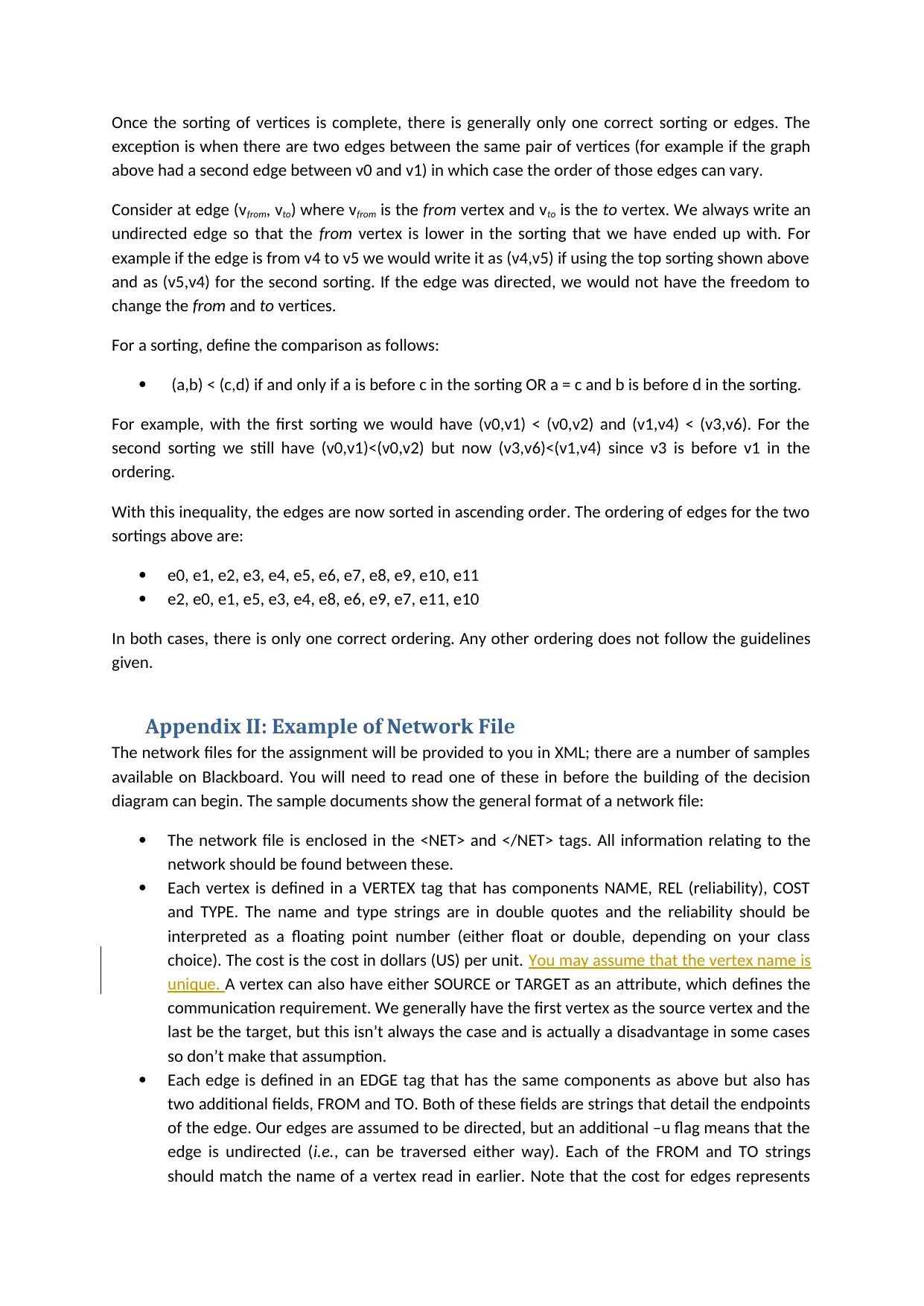
Once the sorting of vertices is complete, there is generally only one correct sorting or edges. The
exception is when there are two edges between the same pair of vertices (for example if the graph
above had a second edge between v0 and v1) in which case the order of those edges can vary.
Consider at edge (vfrom, vto) where vfrom is the from vertex and vto is the to vertex. We always write an
undirected edge so that the from vertex is lower in the sorting that we have ended up with. For
example if the edge is from v4 to v5 we would write it as (v4,v5) if using the top sorting shown above
and as (v5,v4) for the second sorting. If the edge was directed, we would not have the freedom to
change the from and to vertices.
For a sorting, define the comparison as follows:
(a,b) < (c,d) if and only if a is before c in the sorting OR a = c and b is before d in the sorting.
For example, with the first sorting we would have (v0,v1) < (v0,v2) and (v1,v4) < (v3,v6). For the
second sorting we still have (v0,v1)<(v0,v2) but now (v3,v6)<(v1,v4) since v3 is before v1 in the
ordering.
With this inequality, the edges are now sorted in ascending order. The ordering of edges for the two
sortings above are:
e0, e1, e2, e3, e4, e5, e6, e7, e8, e9, e10, e11
e2, e0, e1, e5, e3, e4, e8, e6, e9, e7, e11, e10
In both cases, there is only one correct ordering. Any other ordering does not follow the guidelines
given.
Appendix II: Example of Network File
The network files for the assignment will be provided to you in XML; there are a number of samples
available on Blackboard. You will need to read one of these in before the building of the decision
diagram can begin. The sample documents show the general format of a network file:
The network file is enclosed in the <NET> and </NET> tags. All information relating to the
network should be found between these.
Each vertex is defined in a VERTEX tag that has components NAME, REL (reliability), COST
and TYPE. The name and type strings are in double quotes and the reliability should be
interpreted as a floating point number (either float or double, depending on your class
choice). The cost is the cost in dollars (US) per unit. You may assume that the vertex name is
unique. A vertex can also have either SOURCE or TARGET as an attribute, which defines the
communication requirement. We generally have the first vertex as the source vertex and the
last be the target, but this isn’t always the case and is actually a disadvantage in some cases
so don’t make that assumption.
Each edge is defined in an EDGE tag that has the same components as above but also has
two additional fields, FROM and TO. Both of these fields are strings that detail the endpoints
of the edge. Our edges are assumed to be directed, but an additional –u flag means that the
edge is undirected (i.e., can be traversed either way). Each of the FROM and TO strings
should match the name of a vertex read in earlier. Note that the cost for edges represents

the cost in cents (US) per meter of the component, and this cost can be zero for wireless
connections.
The sample files list all vertices first, and then all edges. This is not necessarily required, but a vertex
must be described before it can be used as the endpoint for an edge. In general, it’s easier to list all
vertices first.
Note that this specification applies only to an unsorted network file. You may store sorted network
files in any format you wish, but choosing a different format means creating a different load method
for sorted files. As with everything, considered relative efficiency.
1 out of 13
Related Documents


Your All-in-One AI-Powered Toolkit for Academic Success.
+13062052269
info@desklib.com
Available 24*7 on WhatsApp / Email
![[object Object]](/_next/static/media/star-bottom.7253800d.svg)
Unlock your academic potential
© 2024 | Zucol Services PVT LTD | All rights reserved.