Products
Study Documents
AI Grader
AI Answer
AI Code Checker
Plagiarism Checker
AI Paraphraser
AI Quiz
AI Detector
Pricing
Blog
About Us
Get 7 Days Free Trial
Login
DIGITAL & ANALOGUE DEVICES & CIRCUITS Assignment 3
Verified
Added on 2023/04/22
|
16
|
2255
|
467
AI Summary
Contribute Materials
Your contribution can guide someone’s learning journey. Share your documents today.
Contribute Now
MODUL
E
TITL
E
:
DIGI
T
A
L
&
ANALOGU
E
DEVICE
S
&
CIRCUITS
T
OPI
C
TITL
E
:
DIGI
T
A
L
DEVICE
S
&
CIRCUITS
TU
T
O
R
MARKE
D
ASSIGNMEN
T
3
(v1.1)
NAM
E
........................................................................................................................................
ADDRES
S
.................................................................................................................................
...................................................................................................................................................
...................................................................................................................................................
......................................................
HOM
E
TELEPHON
E
.....................................................
EMPLOYE
R
..............................................................................................................................
...................................................................................................................................................
...................................................................................................................................................
......................................................
WOR
K
TELEPHON
E
......................................................
Studen
t
declaration:
I
decla
r
e
that
all
the
work
submitted
is
my
own
work
and
that
no
part
of
it
has
been
copied
f
r
om
an
y
othe
r
sou
r
c
e
withou
t
ful
l
acknowledgemen
t
an
d
complie
s
wit
h
th
e
University'
s
guiding
principles
as
stated
in
the
Regulations
Relating
T
o
Academic
Misconduct*.
Studen
t
signatu
r
e
:
.....................................................................................................
Date
:
....................................................................................................
Studen
t
code
:
....................................................................................................
Email
:
....................................................................................................
*
http://www.tees.ac.uk/docs/index.cfm?folder=Student%20Regulations&name=Academic%20Regulations
DAD
C
-
3
-
TM
A
(v1.1)
©
Teesside
University
2011
Secure Best Marks with AI Grader
Need help grading? Try our AI Grader for instant feedback on your assignments.
💎 Get Pro
Published
by
Teesside
University
Open
Learning
(Engineering)
School
of
Science
&
Engineering
Teesside
University
Tees
Valley,
UK
TS1
3BA
+44
(0)1642
342740
All
rights
reserved.
No
part
of
this
publication
may
be
reproduced,
stored
in
a
retrieval
system,
or
transmitted,
in
any
form
or
by
any
means,
electronic,
mechanical,
photocopying,
recording
or
otherwise
without
the
prior
permission
of
the
Copyright
owner.
This
book
is
sold
subject
to
the
condition
that
it
shall
not,
by
way
of
trade
or
otherwise,
be
lent,
re-sold,
hired
out
or
otherwise
circulated
without
the
publisher's
prior
consent
in
any
form
of
binding
or
cover
other
than
that
in
which
it
is
published
and
without
a
similar
condition
including
this
condition
being
imposed
on
the
subsequent
purchaser.
Teesside
University
Open
Learning
(Engineering)
©
Teesside
University
2011
1
IMPO
R
T
ANT
Before
you
start
please
read
the
following
instructions
carefull
y
.
1.
Thi
s
assignmen
t
form
s
par
t
o
f
th
e
forma
l
assessmen
t
fo
r
thi
s
module
.
If
yo
u
fai
l
t
o
reac
h
th
e
require
d
standar
d
fo
r
th
e
assignmen
t
the
n
yo
u
wil
l
be
allowed
to
resubmit
but
a
resubmission
will
only
be
eligible
for
a
Pass
grade
,
no
t
a
Meri
t
o
r
Distinction.
Y
o
u
shoul
d
therefor
e
no
t
submi
t
th
e
assignmen
t
unti
l
yo
u
ar
e
reasonably
sur
e
tha
t
yo
u
hav
e
complete
d
i
t
successfull
y
.
See
k
you
r
tutor'
s
advic
e
if
unsure.
2.
Ensure
that
you
indicate
the
number
of
the
question
you
are
answering.
3.
Mak
e
a
cop
y
o
f
you
r
answer
s
befor
e
submittin
g
th
e
assignment.
4.
Complet
e
al
l
detail
s
o
n
th
e
f
r
on
t
pag
e
o
f
thi
s
TM
A
an
d
retur
n
i
t
with
th
e
completed
assignmen
t
includin
g
supportin
g
calculation
s
where
appropriate
.
Th
e
preferre
d
submissio
n
i
s
vi
a
you
r
TUOL(E
)
Blackboard
account:
https://eat.tees.ac.uk
5.
Y
our
tuto
r
’
s
comments
on
the
assignment
will
be
posted
on
Blackboard.
2
Teesside
University
Open
Learning
(Engineering)
©
Teesside
University
2011
Assessmen
t
Criteria
Thi
s
assignmen
t
take
s
th
e
for
m
o
f
a
desig
n
exercis
e
t
o
a
n
engineerin
g
problem
concerning
a
digital
system.
The
assignment
forms
Element
3
of
the
module
’
s
assessmen
t
criteri
a
tha
t
cover
s
i
n
par
t
Learnin
g
Outcome
s
1
,
2
,
3
an
d
4
as
indicated
belo
w
.
MODUL
E
LEARNIN
G
OUTCOMES
Knowledg
e
an
d
Understanding
1.
Demonstrat
e
a
n
understandin
g
o
f
a
variet
y
o
f
electroni
c
circuit
s
including
power
supplies,
operational
amplifier
circuits
and
digital
logic
circuits.
Cognitiv
e
an
d
Intellectua
l
Skills
2
.
Choos
e
appropriat
e
circui
t
component
s
fo
r
th
e
desig
n
o
f
electroni
c
circuits.
Practica
l
an
d
P
r
ofessiona
l
Skills
3.
Build,
simulate
and
test
simple
electronic
circuits.
Ke
y
T
ransferabl
e
Skills
4.
Demonstrat
e
th
e
applicatio
n
o
f
numerica
l
skill
s
t
o
th
e
solutio
n
o
f
problems
relating
to
digital
and
analogue
devices
and
circuits.
P
ASS
MERIT
Criteri
a
i
n
exces
s
o
f
th
e
pass
grade.
DISTINCTION
Criteri
a
i
n
exces
s
o
f
the
meri
t
grade.
Learnin
g
outcome
s
are
satisfie
d
a
s
evidence
d
by
substantiall
y
correct
understandin
g
o
f
the
operation
and
application
of
simpl
e
operationa
l
amplifier
circuits.
Th
e
transfe
r
o
f
competence
gained
in
one
situation
to
relate
d
bu
t
unfamiliar
circumstances.
The
ability
to
integrate
knowledg
e
fro
m
tw
o
or
mor
e
topi
c
area
s
t
o
solv
e
a
significantly
more
complex
problem.
Paraphrase This Document
Need a fresh take? Get an instant paraphrase of this document with our AI Paraphraser
💎 Try AI Paraphraser
3
Teesside
University
Open
Learning
(Engineering)
©
Teesside
University
2011
Refe
r
t
o
th
e
table
s
a
t
th
e
en
d
o
f
th
e
TM
A
whe
n
answerin
g
Question
s
1
an
d
2.
1.
FIGUR
E
1
show
s
a
n
AL
S
logi
c
circuit
.
Estimate:
(a)
th
e
curren
t
I
OL
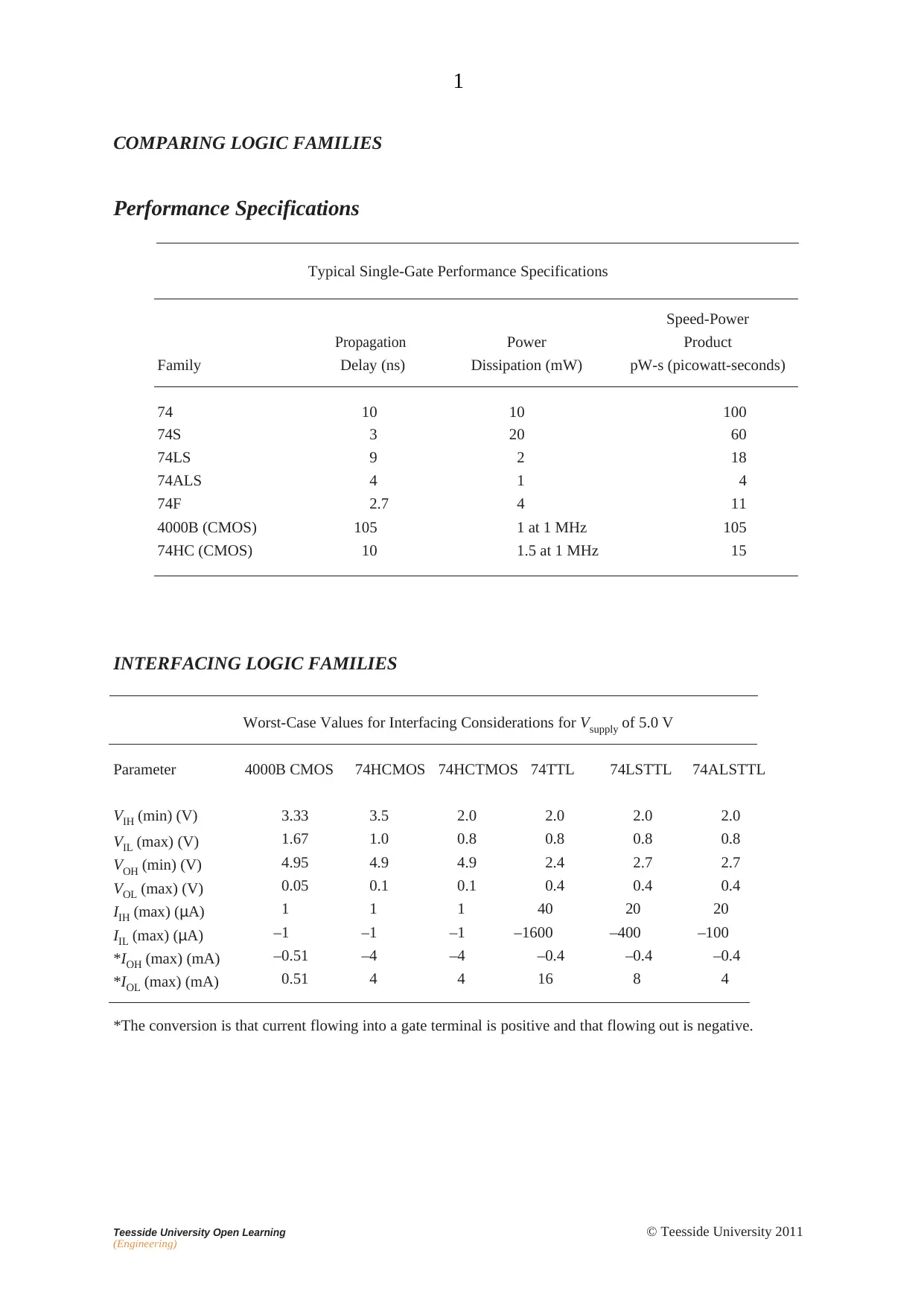
0.4mA as Output from gate. According to INTERFACING LOGIC
FAMILIES Table mentioned in the end of the document
(b)
th
e
dela
y
i
n
a
1-to-
0
transitio
n
a
t
on
e
o
f
th
e
input
s
o
f
G
A
T
E
1
appearin
g
a
s
a
n
e
f
fec
t
a
t
th
e
outpu
t
o
f
G
A
T
E
5.
Propagation delay of one single gate is 4ns. For change in input at
GATE 1 to reflect on output at GATE 5, needs three propagation
delays. So total time is 12ns.
(c)
the
total
power
consumed
by
the
circuit
in
a
quiescent
state.
Each gate has power consumption of 1mW. Total of 5 GATES will
consume 5mW of power.
2
1
I
OL
1
1
1
4
1
5
1
3
1
FIG
.
1
4
Teesside
University
Open
Learning
(Engineering)
©
Teesside
University
2011
2.
(a
)
Explai
n
wit
h
th
e
ai
d
o
f
sketche
s
an
d
b
y
usin
g
a
n
exampl
e
o
f
a
specific
logic
famil
y
,
what
is
meant
by
the
term
‘noise
immunity’.
The signals in gates are propagated and acknowledged based on their
Voltage levels. There is limit where a certain Maximum Voltage is
counted as 0 beyond which it would not be taken as 0 signal.
Similarly there is a minimum Voltage that must appear at input to be
counted as 1. Any Voltage below that level will not get counted as 1.
(05_digital_circuitry.pdf)
The outputs from a gate must confirm to these voltage levels.
However there might be some slight change in actual voltage levels
that appear of input of next Gate. The amount of Voltage fluctuation
that can be handled by a circuit in these expected voltage levels is
called noise immunity of that circuit or Gate.
Like in Diagram the Blue area is the indicator of noise immunity of
the circuit.
(b
)
Explain
,
i
f
an
y
,
th
e
problem
s
associate
d
wit
h
interfacin
g
th
e
logic
families
of
the
circuits
of
FIGURE
2(a)
and
of
FIGURE
2(b).
For
each
circuit,
if
there
is
a
problem
of
interfacing,
give
a
remed
y
.
5
Teesside
University
Open
Learning
(Engineering)
©
Teesside
University
2011
+5
V
+5
V
7404 TTL
(a)
4049B
CMOS
Interfacing of TTL to CMOS needs following 4 conditions to be satisfied:
V
OH
(TTL) ≥ V
IH
(CMOS)
V
OL
(TTL) ≤ V
IL
(CMOS)
-I
OH
(TTL) ≥ I
IH
(CMOS)
I
OL
(TTL) ≥ -I
IL
(CMOS)
The Current levels given in the datasheet confirm the required current conditions are met
when interfacing two families. The Two voltage conditions are however not satisfied. Only
the Low voltage levels are satisfied. The Output High Voltage of the TTL is far less than the
required Minimum voltage. To get the TTL drive a CMOS, a pull up resistor is required that
allows CMOS input to connect to supply voltage. The pull up resistance should be such that
Sink Current in TTL when input is low is within limits of TTL logic.
+5
V
+5
V
4049B
CMOS
7404 TTL
(b)
When interfacing the CMOS to a TTL circuit, the following 4 conditions need to be satisfied:
V
OH
(CMOS) ≥ V
IH
(TTL)
4.95 > 2.0
V
OL
(CMOS) ≤ V
IL
(TTL)
.05 < 0.8
– I
OH
(CMOS) ≥ I
IH
(TTL)
0.51mA > 40uA
I
OL
(CMOS) < – I
IL
(TTL)
0.51mA < 1.6mA
Given data in the datasheet, confirms the ability of CMOS driver to provide sufficient Voltage levels to
count as logic 1 or 0 at the input of TTL device. Both limits are well within range of the required
values. The Current requirements of the driver also needs to be considered in this case. The current
for logic 1 is sufficiently large current for logic 0 is also well beyond maximum value allowed by TTL. So
device can connect directly without any other component.
Secure Best Marks with AI Grader
Need help grading? Try our AI Grader for instant feedback on your assignments.
💎 Get Pro
6
Teesside
University
Open
Learning
(Engineering)
©
Teesside
University
2011
3.
Th
e
bloc
k
diagra
m
o
f
FIGUR
E
3
show
s
a
three-stag
e
asynchrononous
counte
r
tha
t
i
s
use
d
t
o
coun
t
a
serie
s
o
f
randoml
y
occurrin
g
inpu
t
pulses.
Th
e
‘Q
’
output
s
o
f
th
e
counte
r
ar
e
use
d
t
o
driv
e
a
logi
c
circui
t
tha
t
gives
the
output shown
in
T
ABLE
1.
(a)
Desig
n
th
e
counte
r
usin
g
typ
e
D
flip-flop
s
an
d
simulat
e
you
r
design
i
n
PSpice
,
producin
g
waveform
s
t
o
confir
m
th
e
circuit
’
s
operation.
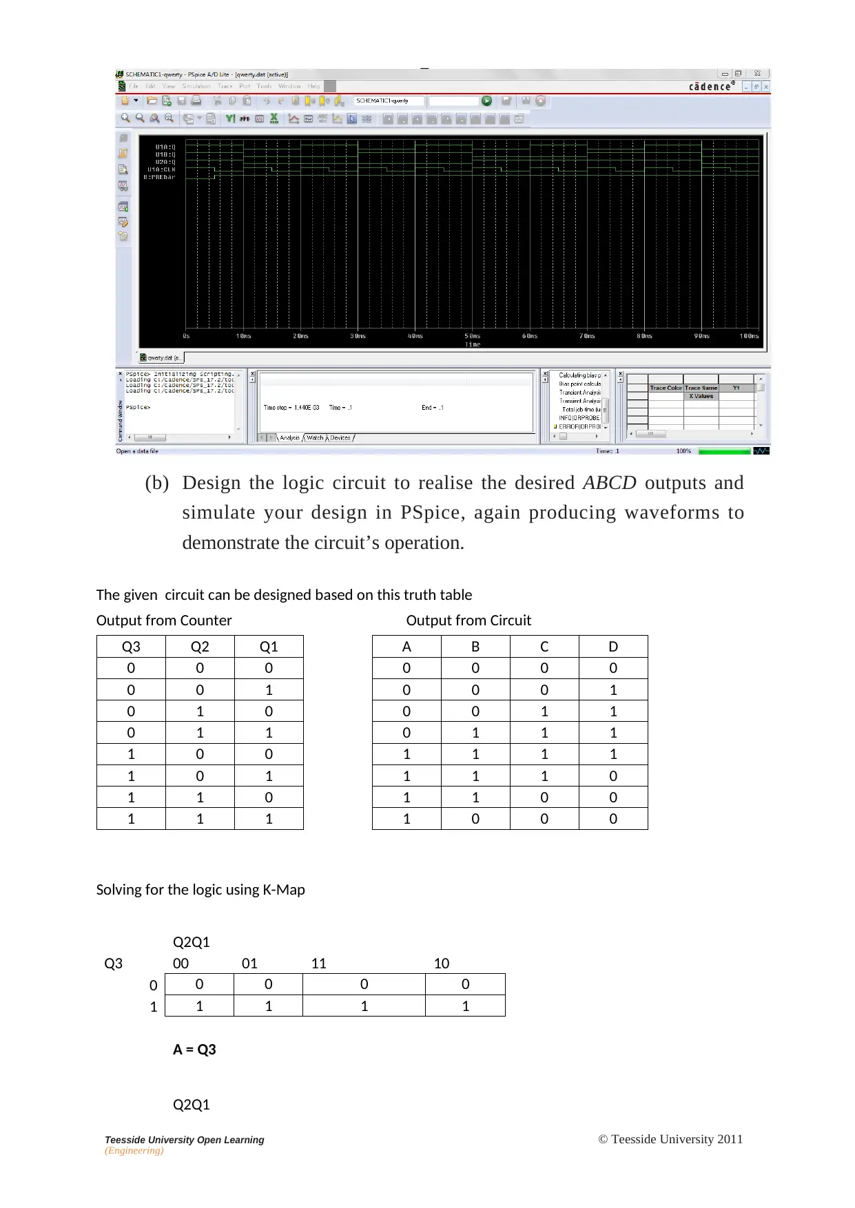
The circuit is an asynchronous UP counter using 3 D flip flops.
Initially a logic 0 is applied to the PRE pins of the flops. This resets
all flip flops. Then Inverted output of each flip flop is connected to
the input of the same flip flop. This helps toggle the flip flop in each
input clock. The asynchronous impulse input is used as clock to drive
the D flip flop. Output of the First stage is used as input clock for the
second clock. This makes a 3 bit asynchronous counter. The results
are available as Q1, Q2 and Q3. The same is visible in waveform
shown below.
7
Teesside
University
Open
Learning
(Engineering)
©
Teesside
University
2011
(b)
Desig
n
th
e
logi
c
circui
t
t
o
realis
e
th
e
desire
d
ABC
D
output
s
and
simulat
e
you
r
desig
n
i
n
PSpice
,
agai
n
producin
g
waveform
s
to
demonstrat
e
th
e
circuit
’
s
operation.
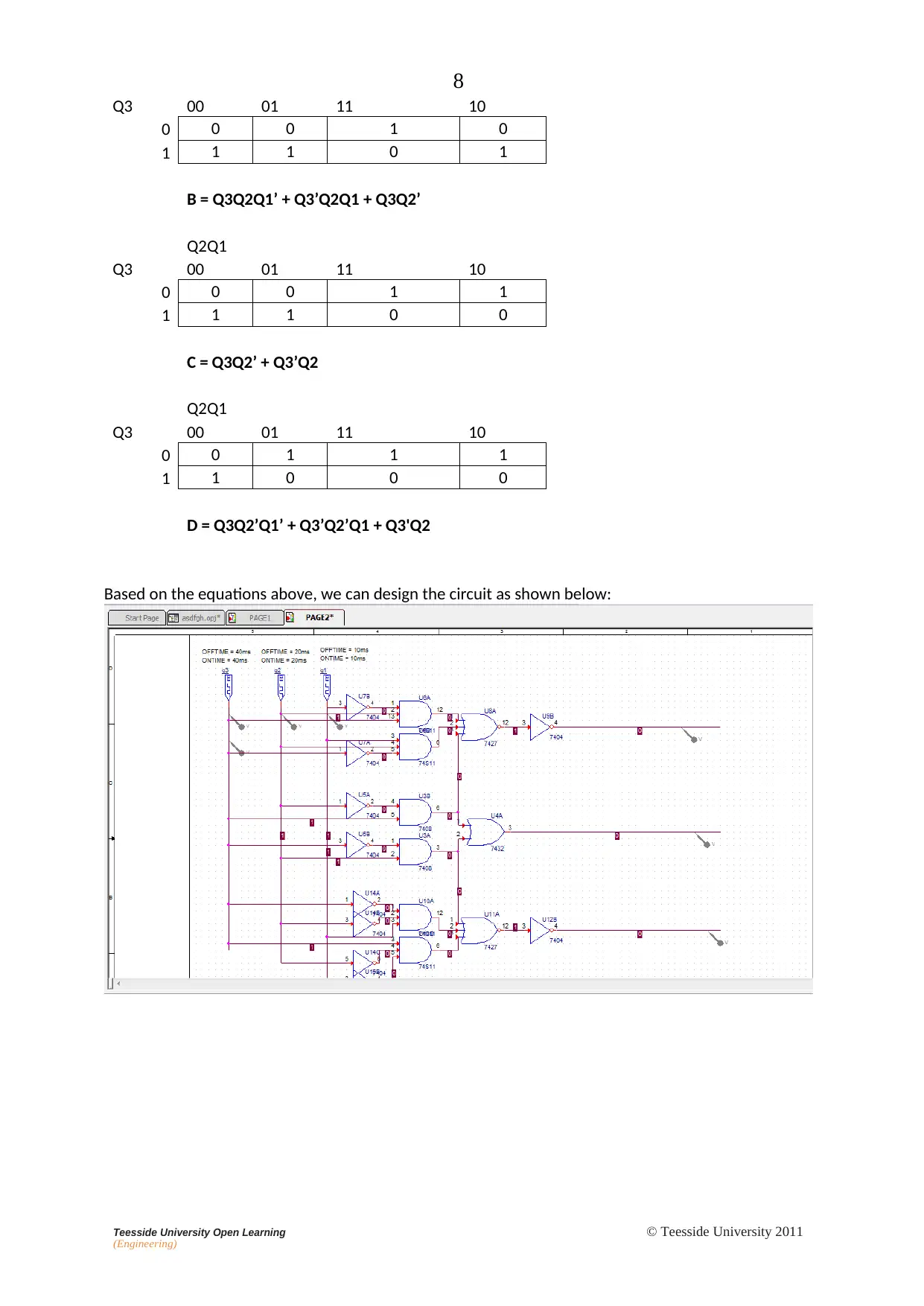
The given circuit can be designed based on this truth table
Output from Counter
Output from Circuit
Q3
Q2
Q1
A
B
C
D
0
0
0
0
0
0
0
0
0
1
0
0
0
1
0
1
0
0
0
1
1
0
1
1
0
1
1
1
1
0
0
1
1
1
1
1
0
1
1
1
1
0
1
1
0
1
1
0
0
1
1
1
1
0
0
0
Solving for the logic using K-Map
Q2Q1
Q3
00
01
11
10
0
0
0
0
0
1
1
1
1
1
A = Q3
Q2Q1
8
Teesside
University
Open
Learning
(Engineering)
©
Teesside
University
2011
Q3
00
01
11
10
0
0
0
1
0
1
1
1
0
1
B = Q3Q2Q1’ + Q3’Q2Q1 + Q3Q2’
Q2Q1
Q3
00
01
11
10
0
0
0
1
1
1
1
1
0
0
C = Q3Q2’ + Q3’Q2
Q2Q1
Q3
00
01
11
10
0
0
1
1
1
1
1
0
0
0
D = Q3Q2’Q1’ + Q3’Q2’Q1 + Q3'Q2
Based on the equations above, we can design the circuit as shown below:
Paraphrase This Document
Need a fresh take? Get an instant paraphrase of this document with our AI Paraphraser
💎 Try AI Paraphraser
9
Teesside
University
Open
Learning
(Engineering)
©
Teesside
University
2011
Logic
1
0
Teesside
University
Open
Learning
(Engineering)
©
Teesside
University
2011
In
Counter
t
Q1
Q2
Q3
A
B
C
D
FIG
.
3
Input
pulse
D
C
B
A
0
0
0
0
0
1
0
0
0
1
2
0
0
1
1
3
0
1
1
1
4
1
1
1
1
5
1
1
1
0
6
1
1
0
0
7
1
0
0
0
8
0
0
0
0
9
0
0
0
1
etc
T
ABL
E
1
1
1
Teesside
University
Open
Learning
(Engineering)
©
Teesside
University
2011
COM
P
ARIN
G
LOGI
C
F
AMILIES
Performanc
e
Specifications
Typical
Single-Gate
Performance
Specifications
Family
Propagation
Delay
(ns)
Power
Dissipation
(mW)
Speed-Power
Product
pW-s
(picowatt-seconds)
74
10
10
100
74S
3
2
0
6
0
74LS
9
2
18
74ALS
4
1
4
74F
2.7
4
11
4000B
(CMOS)
105
1
at 1
MHz
105
74HC
(CMOS)
10
1.5
at 1
MHz
15
INTER
F
ACIN
G
LOGI
C
F
AMILIES
Worst-Case
Values
for
Interfacing
Considerations
for
V
supply
of
5.0
V
Parameter
4000B
CMOS
74HCMOS
74HCTMOS
74TTL
74LSTTL
74ALSTTL
V
I
H
(min)
(V)
3.33
3.5
2.0
2.0
2.0
2.0
V
I
L
(max)
(V)
1.67
1.0
0.8
0.8
0.8
0.8
V
O
H
(min)
(V)
4.95
4.9
4.9
2.4
2.7
2.7
V
O
L
(max)
(V)
0.05
0.1
0.1
0.4
0.4
0.4
I
I
H
(max
)
(
μ
A)
1
1
1
40
20
20
I
I
L
(max
)
(
μ
A)
–1
–1
–1
–1600
–400
–100
*
I
O
H
(max)
(mA)
–0.51
–4
–4
–0.4
–0.4
–0.4
*
I
O
L
(max)
(mA)
0.51
4
4
16
8
4
*The
conversion
is
that
current
flowing
into
a
gate
terminal
is
positive
and
that
flowing
out
is
negative.
Secure Best Marks with AI Grader
Need help grading? Try our AI Grader for instant feedback on your assignments.
💎 Get Pro
©
Teesside
University
2011
Teesside
University
Open
Learning
(Engineering)
Question
No.
Teesside
University
Open
Learning
(Engineering)
©
Teesside
University
2011
Question
No.
Teesside
University
Open
Learning
(Engineering)
©
Teesside
University
2011
Question
No.
1 out of 16
Download
Related Documents
Sequential Logic Design for Analogue and Digital Electronics
|
5
|
1281
|
238
View Document
(MKT6035)-International Marketing Planning Assessment
|
7
|
3034
|
155
View Document
(MKT 6044)-Birmingham City Business School Assessment Brief for Business Development
|
8
|
3289
|
441
View Document
Designing and Implementing a Graphical User Interface for Data Structures
|
8
|
2110
|
215
View Document
Apply Fluid and Thermodynamics Principles in Engineering - Assignment Part B
|
22
|
4839
|
87
View Document