Forensic Engineering Failure Analysis and Prevention
VerifiedAdded on 2023/04/23
|14
|3504
|175
AI Summary
The power plant gas turbine blades are exposed to extreme conditions of operation. This leads to different forms of failure such as erosion, fatigue, and thermal stresses. In order to encounter all these stresses, there has been the development of newer super alloy perfect metallurgical properties. The failure of the blade of the power plant turbine was as a result of multiple mechanisms of failure including fatigue, thermal stress, and erosion. In order to correct the situation, there are suggested solutions including advanced techniques for cooling and coating.
Contribute Materials
Your contribution can guide someone’s learning journey. Share your
documents today.
FORENSIC ENGINEERING FAILURE ANALYSIS AND PREVENTION
By Name
Course
Instructor
Institution
Location
Date
By Name
Course
Instructor
Institution
Location
Date
Secure Best Marks with AI Grader
Need help grading? Try our AI Grader for instant feedback on your assignments.
Contents
Abstract.......................................................................................................................................................4
Introduction.................................................................................................................................................5
Case Study Overview...................................................................................................................................6
Blade Degradation and Modes of failure.....................................................................................................8
Erosion.....................................................................................................................................................8
Fatigue.....................................................................................................................................................9
Thermal stresses....................................................................................................................................10
Cooling Techniques................................................................................................................................11
Regulations and Principles.....................................................................................................................12
Conclusion.................................................................................................................................................13
REFERENCES..............................................................................................................................................14
Abstract
As the demand of power supply increases, more efficient engines of the turbojet become
common. The design of the engines of the power plant gas turbine is pushed to its extreme
boundary conditions. As compared to machines of the previous decades, the turbomachines are
becoming larger and larger. As a result of increase in size, the failure chances also increase.
Among all other components of the power plant gas turbine, it is the blade that is exposed to the
extreme conditions of the operations. The blade, therefore, experiences different forms of failure.
Constant thermal and other mechanical stresses continuously act on various parts of the blade. In
order to encounter all these stresses, there has been the development of newer super alloy perfect
metallurgical properties. Actually, these new technologies are being tested to confirm their
suitability for these kinds of operations. It has been found out that most of the failures in the
blades of power plant gas turbine are as a result of high temperatures of operation. This effect
can be corrected up to some limit. This means that there is a need for thermal protection to be
provided to the blades at all times. In order to correct the situation, there are suggested solutions
including advanced techniques for cooling and coating. Various types of literature have been
combining parameters in order to provide convincing data on the mitigation measures.
Introduction
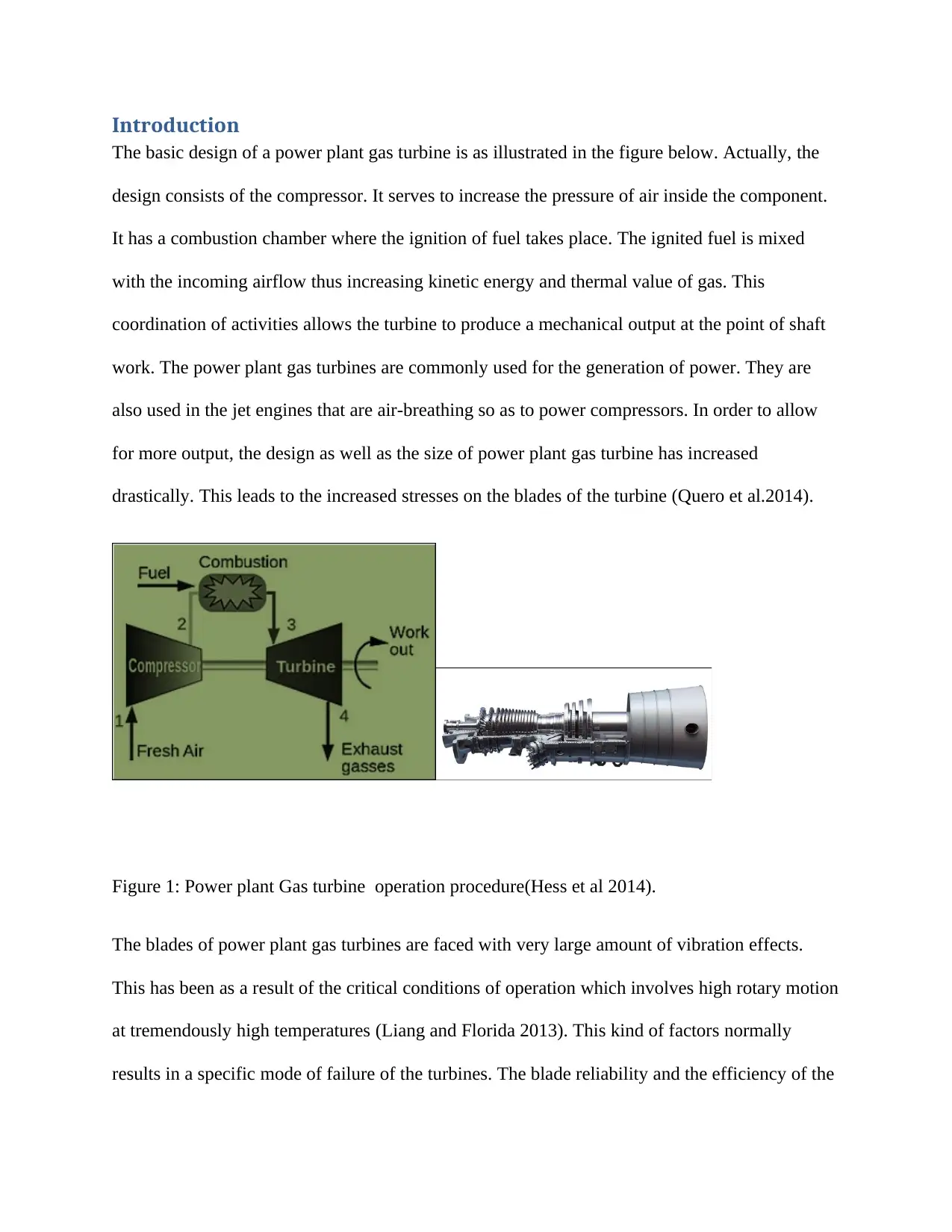
The basic design of a power plant gas turbine is as illustrated in the figure below. Actually, the
design consists of the compressor. It serves to increase the pressure of air inside the component.
It has a combustion chamber where the ignition of fuel takes place. The ignited fuel is mixed
with the incoming airflow thus increasing kinetic energy and thermal value of gas. This
coordination of activities allows the turbine to produce a mechanical output at the point of shaft
work. The power plant gas turbines are commonly used for the generation of power. They are
also used in the jet engines that are air-breathing so as to power compressors. In order to allow
for more output, the design as well as the size of power plant gas turbine has increased
drastically. This leads to the increased stresses on the blades of the turbine (Quero et al.2014).
Figure 1: Power plant Gas turbine operation procedure(Hess et al 2014).
The blades of power plant gas turbines are faced with very large amount of vibration effects.
This has been as a result of the critical conditions of operation which involves high rotary motion
at tremendously high temperatures (Liang and Florida 2013). This kind of factors normally
results in a specific mode of failure of the turbines. The blade reliability and the efficiency of the
Secure Best Marks with AI Grader
Need help grading? Try our AI Grader for instant feedback on your assignments.
blade reduce as a result of the metallurgical anomalies like corrosion, fatigue, erosion, and creep.
The other factors may include airborne pollutants, irresponsible operating, foreign objects and
poor manufacturing. Fatigue and corrosion are the main issues that have been analyzed and
considered as the main concerns in improving and enhancing operating life and durability of the
turbine blades. The material used for the construction of the blades of the power plant gas turbine
is expected to be heat resistant and hard. This means they should have very high melting points
and also have high resistance to corrosion. This is the main reasons why nickel-based and cobalt-
based alloys are commonly used.
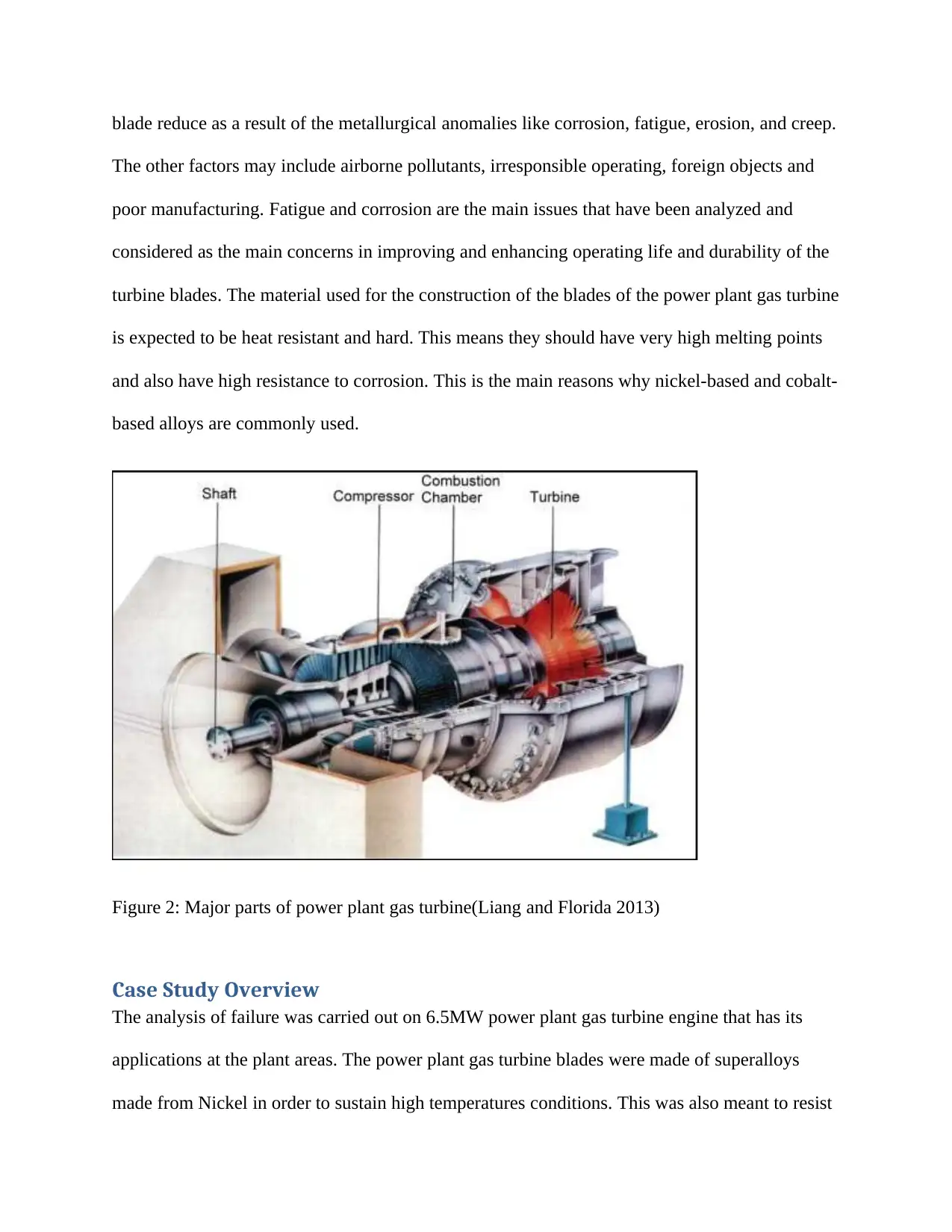
Figure 2: Major parts of power plant gas turbine(Liang and Florida 2013)
Case Study Overview
The analysis of failure was carried out on 6.5MW power plant gas turbine engine that has its
applications at the plant areas. The power plant gas turbine blades were made of superalloys
made from Nickel in order to sustain high temperatures conditions. This was also meant to resist
environmental conditions that are normally corrosive. The microstructural evaluation of the
material of the blade indicated that there was no micro-structural damage that took place as a
result of the blade operation at very high temperatures. This was carried out specifically at the
points around midspan, root, and tip. This indicated that the design of the power plant gas turbine
blade was to allow it to be operated at normal conditions. The blades of the power plant gas
turbine might have suffered due to the HTHC and LTHC corrosion and thermal stress. During
the study, it was revealed that bade was rough at the root section. It was also characterized by
changes in color.This was an indication of low-temperature hot corrosion at this specific point of
the blade (Liu, Jiang, Xiong and Wang 2013).
At the areas around the tip of the blade, it was discovered that there was a reduction of thickness
and material loss. This was an indication that the tip of the blade might have been subjected to a
combined mechanism of fatigue and hot corrosion. The green colorization at the tip was an
indication of the possible occurrence of thermal stress. The study further revealed that the blade
was subject to erosion by various particulate matters. The possible sources of the particulate
matter might be from the casing of the compressor during the process of compression. The
conclusion in the case study was that the failure of the blade of the power plant turbine was as a
result of multiple mechanisms of failure including fatigue, thermal stress, and erosion (Liang and
Florida 2014).The failed blades had visible cracks at the points of their roots which were
initiating at the trailing edge. The concave side of the steeple outermost radius was the seriously
affected component. It was therefore crucial for the process of investigation to include
metallographic analysis of the cracked blades. The other types of the investigation which were
considered relevant for the study included the blade stress analysis, natural test and frequency
analysis, the unit operation parameters and the events history, crack propagation analysis and
finally fracture mechanics. This particular paper provides an overview of this kind of failure
with the recommendation of some of the remedial measures which out to have been effected.
Blade Degradation and Modes of failure
The power plant gas turbine blade is normally subjected to very extreme conditions. These
conditions are responsible for the degradation of the blades. The occurrence of the damage may
be a result of the metallurgical properties of the materials or the mechanical behavior of the
component that affect the life of the materials. Due to the oscillatory actions of the component,
the formation of the crack may be found to be very significant in the process (Hess et al.2014).
Erosion
The occurrence of erosion is associated with the removal of the material from the surface of the
component by the action of a moving fluid or solid ate very high velocities. This leads to very
high loss of the materials as a result of erosion (Virkler 2014). It is important that the flow of the
fluids may be accompanied by the presence of other foreign particles or the unwanted materials
which cause faster deformation and cutting to not only the blades of the power plant gas turbine
but also other components of the gas turbine engine. Since the last decade of the design of the
gas turbines, erosions have been a source of concern. Actually, the economic aspect and
efficiency of the blade normally rely on the erosion effect. Some scholars have stated that
erosion is basically a complex function of the velocity of the particle, the target properties, angle,
and the material type. The erosion of alloys of ductile materials and the component itself can be
predicted by use of the model of the model of Grant-Taboff (Huang et al.2018).
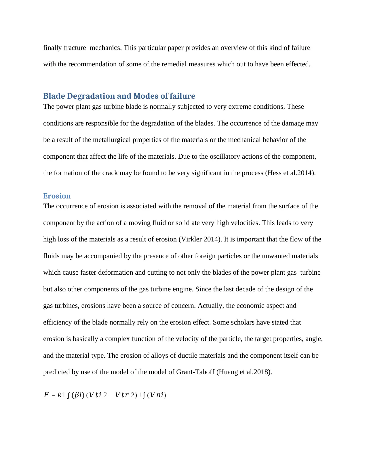
𝐸 = 𝑘1 ʄ (𝛽𝑖) (𝑉𝑡𝑖 2 − 𝑉𝑡𝑟 2) +ʄ (𝑉𝑛𝑖)
Paraphrase This Document
Need a fresh take? Get an instant paraphrase of this document with our AI Paraphraser
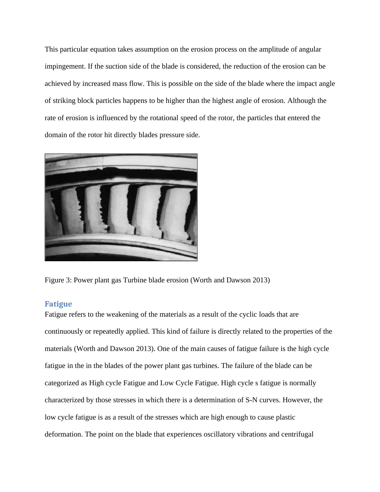
This particular equation takes assumption on the erosion process on the amplitude of angular
impingement. If the suction side of the blade is considered, the reduction of the erosion can be
achieved by increased mass flow. This is possible on the side of the blade where the impact angle
of striking block particles happens to be higher than the highest angle of erosion. Although the
rate of erosion is influenced by the rotational speed of the rotor, the particles that entered the
domain of the rotor hit directly blades pressure side.
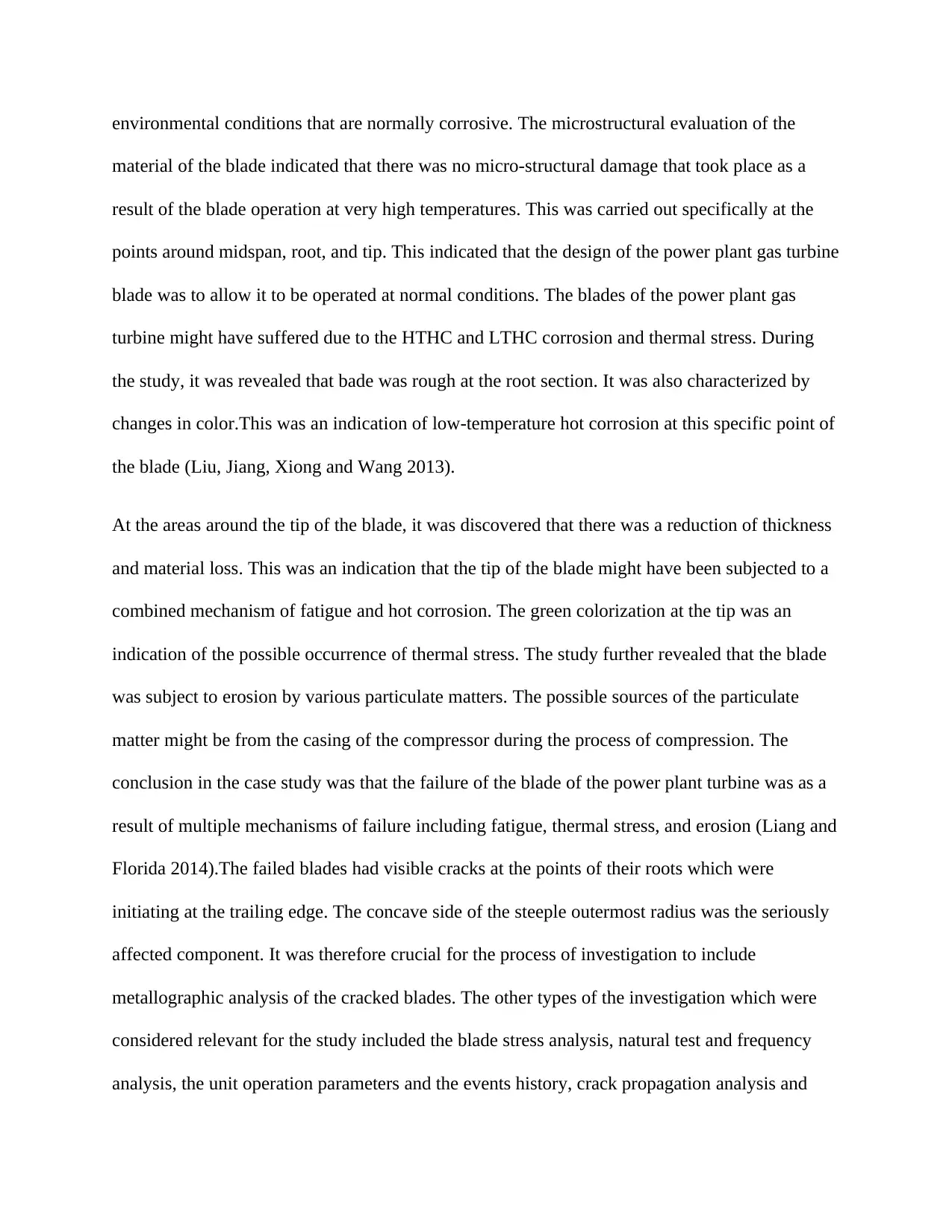
Figure 3: Power plant gas Turbine blade erosion (Worth and Dawson 2013)
Fatigue
Fatigue refers to the weakening of the materials as a result of the cyclic loads that are
continuously or repeatedly applied. This kind of failure is directly related to the properties of the
materials (Worth and Dawson 2013). One of the main causes of fatigue failure is the high cycle
fatigue in the in the blades of the power plant gas turbines. The failure of the blade can be
categorized as High cycle Fatigue and Low Cycle Fatigue. High cycle s fatigue is normally
characterized by those stresses in which there is a determination of S-N curves. However, the
low cycle fatigue is as a result of the stresses which are high enough to cause plastic
deformation. The point on the blade that experiences oscillatory vibrations and centrifugal
effects especially the regions of the blade that are in contact with the disc are some of the most
vulnerable locations which are at risk of fatigue cracking.
The reduction in fatigue life is seriously caused by the micro slip. This is normally experienced
by the surfaces in contact when they are further subjected to fatigue. This kind of phenomenon is
known as fretting fatigue. Fretting fatigue is the common cause of the increased shear stresses
and tensile impacts with results into the genesis of the crack, its subsequent growth and finally
fractures. The propagation of the gradient of the fret crack is normally dependent on the gradient
of the stress, the contacts shape, friction coefficient and finally the applied load. In order to
increase the material or the resistance of the component to this kind fatigue, the roots joints of
the compressor blades should be coated with the Cu-Ni-In. This coating is normally regarded as
effective for the resistance to fatigue (Virkler and Gates 2014).
Thermal stresses
A very large amount of thermal stresses are normally experienced by the power plant gas turbine
blades as a result of the direct exposure to gases that are at temperature. Those components that
are regarded as the first stage of the power plant gas turbine are normally subjected to a large
number of thermal loads. This leads to thermal fatigue and creep (Botta et al 2013). Particularly
the tips of the blades experience large thermal loads leading to leakages in the flow created by
the shrouded casing and the blade tip. The large gradient of the pressure between the side of the
pressure and side of the suction results into the loss of power and reduced efficiency of the blade.
The failures of any single crystal that are solidified by the alloy is as a result of the cracks that
are caused due to cracks of thermal stress origin. The failure of the alloy will depend on the
cyclic loading taking place at very high temperatures (Nagesh, Basha and Singh 2015).
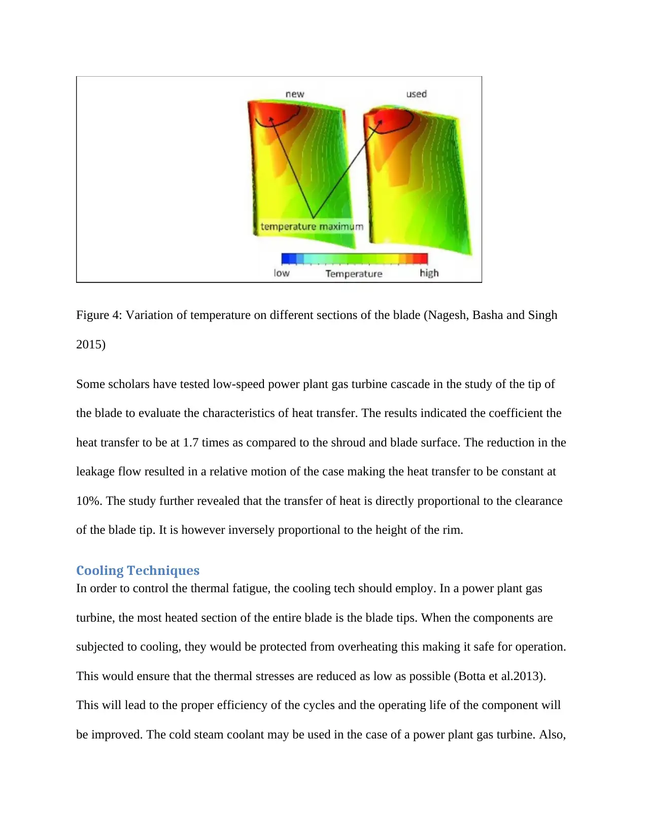
Figure 4: Variation of temperature on different sections of the blade (Nagesh, Basha and Singh
2015)
Some scholars have tested low-speed power plant gas turbine cascade in the study of the tip of
the blade to evaluate the characteristics of heat transfer. The results indicated the coefficient the
heat transfer to be at 1.7 times as compared to the shroud and blade surface. The reduction in the
leakage flow resulted in a relative motion of the case making the heat transfer to be constant at
10%. The study further revealed that the transfer of heat is directly proportional to the clearance
of the blade tip. It is however inversely proportional to the height of the rim.
Cooling Techniques
In order to control the thermal fatigue, the cooling tech should employ. In a power plant gas
turbine, the most heated section of the entire blade is the blade tips. When the components are
subjected to cooling, they would be protected from overheating this making it safe for operation.
This would ensure that the thermal stresses are reduced as low as possible (Botta et al.2013).
This will lead to the proper efficiency of the cycles and the operating life of the component will
be improved. The cold steam coolant may be used in the case of a power plant gas turbine. Also,
Secure Best Marks with AI Grader
Need help grading? Try our AI Grader for instant feedback on your assignments.
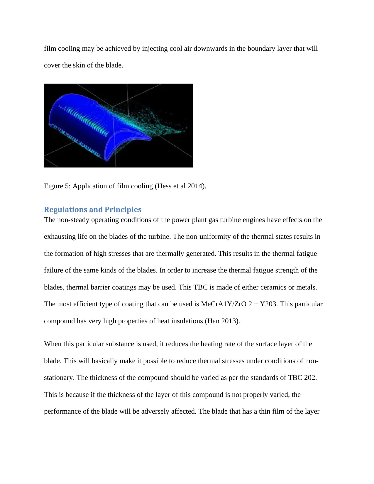
film cooling may be achieved by injecting cool air downwards in the boundary layer that will
cover the skin of the blade.
Figure 5: Application of film cooling (Hess et al 2014).
Regulations and Principles
The non-steady operating conditions of the power plant gas turbine engines have effects on the
exhausting life on the blades of the turbine. The non-uniformity of the thermal states results in
the formation of high stresses that are thermally generated. This results in the thermal fatigue
failure of the same kinds of the blades. In order to increase the thermal fatigue strength of the
blades, thermal barrier coatings may be used. This TBC is made of either ceramics or metals.
The most efficient type of coating that can be used is MeCrA1Y/ZrO 2 + Y203. This particular
compound has very high properties of heat insulations (Han 2013).
When this particular substance is used, it reduces the heating rate of the surface layer of the
blade. This will basically make it possible to reduce thermal stresses under conditions of non-
stationary. The thickness of the compound should be varied as per the standards of TBC 202.
This is because if the thickness of the layer of this compound is not properly varied, the
performance of the blade will be adversely affected. The blade that has a thin film of the layer
will concentrate a large amount of heat leading to a devastating failure (Krewinkel 2013). The
law of variation along the blade contour musty is followed under the stated boundary conditions.
Studies have indicated that failures of the power plant gas turbine that have been secured using
TBC are normally very devastating. The accumulation of heat at one specific location leaves the
component in a state beyond repair. This may include the use of a replacement technique which
is expensive as well. An increase in the wall thickness of the local blade in the regions that have
a very high coefficient of heat transfer would equalize the temperatures even in the homochronic
processes. When the variation is done, there will be disruption to these effects. The problem will,
therefore, be solved through strict adherence to the stipulated standards (Lörstad, et al 2013)...
Conclusion
From the study that was conducted, it is possible to conclude that mechanical and metallurgical
causes of power plant turbine blade failure will always be present. It was observed that the major
contributor to the degradation of the blade quality is the extremely high temperatures gases that
flow over the blades. Actually, these new technologies are being tested to confirm their
suitability for these kinds of operations (Botta et al. 2013). It has been found out that most of the
failures in the blades of the power plant gas turbine are as a result of the high temperatures of
operation. This effect can be corrected up to some limit. This means that there is a need for
thermal protection to be provided to the blades at all times. This actually reduces the possibilities
of thermal protection of the components of the power plant gas turbine failure. The main areas of
research should, therefore, be the advanced thermal protection mechanisms. The thermal barrier
coating concept may be considered a Nobel idea of handling the effects of thermal stresses.
REFERENCES
Botta, F., Dini, D., Schwingshackl, C., di Mare, L. and Cerri, G., 2013. Optimal placement of
piezoelectric plates to control multimode vibrations of a beam. Advances in Acoustics and
Vibration, 2013.
Botta, F., Marx, N., Schwingshackl, C., Cerri, G. and Dini, D., 2013, June. A wireless vibration
control technique for gas turbine blades using piezoelectric plates and contactless energy
transfer. In ASME Turbo Expo 2013: Turbine Technical Conference and Exposition (pp.
V07AT32A006-V07AT32A006). American Society of Mechanical Engineers.
Han, J.C., 2013. Fundamental gas turbine heat transfer. Journal of thermal science and
engineering applications, 5(2), p.021007.
Hess, J.R., Haribhau, N., Crum, G.A., Seale, J.A. and Hogg, D.W., General Electric Co,
2014. Gas turbine half-casing shipping fixture. U.S. Patent 8,876,448.
Huang, G., Min, Z., Yang, L., Jiang, P.X. and Chyu, M., 2018. Transpiration cooling for additive
manufactured porous plates with partition walls. International Journal of Heat and Mass
Transfer, 124, pp.1076-1087.
Krewinkel, R., 2013. A review of gas turbine effusion cooling studies. International Journal of
Heat and Mass Transfer, 66, pp.706-722.
Liang, G., Florida Turbine Technologies Inc, 2013. Turbine vane with mate face seal. U.S.
Patent 8,430,626.
Liang, G., Florida Turbine Technologies Inc, 2014. Industrial turbine stator vane. U.S. Patent
8,870,524.
Paraphrase This Document
Need a fresh take? Get an instant paraphrase of this document with our AI Paraphraser
Liu, Y.Q., Jiang, P.X., Xiong, Y.B. and Wang, Y.P., 2013. Experimental and numerical
investigation of transpiration cooling for sintered porous flat plates. Applied Thermal
Engineering, 50(1), pp.997-1007.
Lörstad, D., Lindholm, A., Pettersson, J., Björkman, M. and Hultmark, I., 2013, June. Siemens
SGT-800 industrial gas turbine enhanced to 50MW: Combustor design modifications, validation,
and operation experience. In ASME Turbo Expo 2013: Turbine Technical Conference and
Exposition (pp. V01BT04A038-V01BT04A038). American Society of Mechanical Engineers.
Nagesh, S., Basha, A.J. and Singh, T.D., 2015. Dynamic performance analysis of high-speed
flexible coupling of gas turbine engine transmission system. Journal of Mechanical Science and
Technology, 29(1), pp.173-179.
Quero, M., Korzynietz, R., Ebert, M., Jiménez, A.A., Del Río, A. and Brioso, J.A., 2014.
Solugas–Operation experience of the first solar hybrid gas turbine system at MW scale. Energy
Procedia, 49, pp.1820-1830.
Virkler, S.D. and Gates, R., United Technologies Corp, 2014. Cover plate with an interstage seal
for a gas turbine engine. U.S. Patent 8,740,554.
Virkler, S.D., United Technologies Corp, 2014. Component lock for a gas turbine engine. U.S.
Patent 8,840,375.
Worth, N.A. and Dawson, J.R., 2013. Self-excited circumferential instabilities in a model
annular gas turbine combustor: Global flame dynamics. Proceedings of the Combustion
Institute, 34(2), pp.3127-3134.
1 out of 14
Related Documents
Your All-in-One AI-Powered Toolkit for Academic Success.
+13062052269
info@desklib.com
Available 24*7 on WhatsApp / Email
![[object Object]](/_next/static/media/star-bottom.7253800d.svg)
Unlock your academic potential
© 2024 | Zucol Services PVT LTD | All rights reserved.


