Optical Signal Splitting and Combining Lab Report
Added on 2023-06-12
11 Pages2183 Words76 Views
UNIVERSITY AFFILIATION
DEPARTMENT OR FACULTY
COURSE ID & NAME
TITLE:
OPTICAL SIGNAL SPLITTING AND COMBINING LAB
REPORT
STUDENT NAME
STUDENT REGISTRATION NUMBER
PROFESSOR (TUTOR)
DATE OF SUBMISSION
DEPARTMENT OR FACULTY
COURSE ID & NAME
TITLE:
OPTICAL SIGNAL SPLITTING AND COMBINING LAB
REPORT
STUDENT NAME
STUDENT REGISTRATION NUMBER
PROFESSOR (TUTOR)
DATE OF SUBMISSION

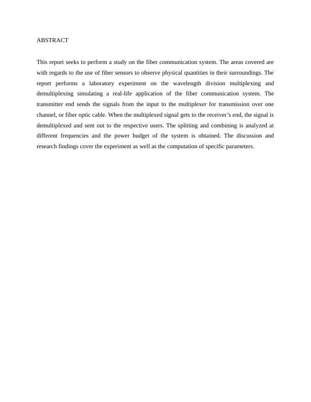
ABSTRACT
This report seeks to perform a study on the fiber communication system. The areas covered are
with regards to the use of fiber sensors to observe physical quantities in their surroundings. The
report performs a laboratory experiment on the wavelength division multiplexing and
demultiplexing simulating a real-life application of the fiber communication system. The
transmitter end sends the signals from the input to the multiplexer for transmission over one
channel, or fiber optic cable. When the multiplexed signal gets to the receiver’s end, the signal is
demultiplexed and sent out to the respective users. The splitting and combining is analyzed at
different frequencies and the power budget of the system is obtained. The discussion and
research findings cover the experiment as well as the computation of specific parameters.

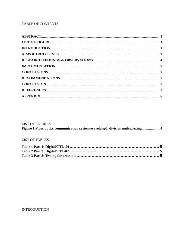
TABLE OF CONTENTS
ABSTRACT....................................................................................................................................1
LIST OF FIGURES.......................................................................................................................1
INTRODUCTION.........................................................................................................................1
AIMS & OBJECTIVES................................................................................................................3
RESEARCH FINDINGS & OBSERVATIONS..........................................................................4
IMPLEMENTATION....................................................................................................................5
CONCLUSIONS............................................................................................................................5
RECOMMENDATIONS...............................................................................................................5
CONCLUSION..............................................................................................................................5
REFERENCES..............................................................................................................................5
APPENDIX.....................................................................................................................................6
LIST OF FIGURES
Figure 1 Fiber optics communication system-wavelength division multiplexing....................4
LIST OF TABLES
Table 1 Part 1: Digital/TTL -01.................................................................5
Table 2 Part 2: Digital/TTL-02..................................................................5
Table 3 Part 3: Testing for crosstalk............................................................5
INTRODUCTION

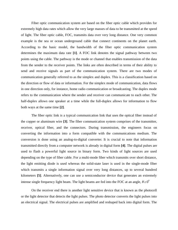
Fiber optic communication system are based on the fiber optic cable which provides for
extremely high data rates which allow the very large masses of data to be transmitted at the speed
of light. The fiber optic cable, FOC, transmits data over very long distance. One very common
example is the sea or ocean underground cable that connect continents on the planet earth.
According to the basic model, the bandwidth of the fiber optic communication system
determines the maximum data rate [1]. A FOC link denotes the signal pathway between two
points using the cable. The pathway is the mode or channel that enables transmission of the data
from the sender to the receiver points. The links are often described in terms of their ability to
send and receive signals as part of the communication system. There are two modes of
communication generally referred to as the simplex and duplex. This is a classification based on
the direction or flow of data or information. For the simplex mode of communication, data flows
in one direction only, for instance, home radio communication or broadcasting. The duplex mode
refers to the communication where the sender and receiver can communicate to each other. The
half-duplex allows one speaker at a time while the full-duplex allows for information to flow
both ways at the same time [2].
The fiber optic link is a typical communication link that uses the optical fiber instead of
the copper or aluminum wire [3]. The fiber communication system comprises of the transmitter,
receiver, optical fiber, and the connectors. During transmission, the engineers focus on
converting the information into a form compatible with the communications medium. The
conversion is done using an analog-to-digital converter. It is crucial to note that information
transmitted directly from a computer network is already in digital form [4]. The digital pulses are
used to flash a powerful light source in binary form. Two kinds of light sources are used
depending on the type of fiber cable. For a multi-mode fiber which transmits over short distance,
the light emitting diode is used whereas the solid-state laser is used in the single-mode fiber
which transmits a single information signal over very long distances, up to several hundred
kilometers [5]. Alternatively, one can use a semiconductor device that generates an extremely
intense single frequency light beam. The light beams are fed into the FOC at an angle, θ ≥ 00
On the receiver end there is another light sensitive device that is known as the photocell
or the light detector that detects the light pulses. The photo detector converts the light pulses into
an electrical signal. The electrical pulses are amplified and reshaped back into digital form. The

End of preview
Want to access all the pages? Upload your documents or become a member.
Related Documents
Fiber Communication System: Optical Sensors and Multiplexing Mechanismslg...
|14
|2451
|180
Fiber Optic Communication Systems: Technical Aspects and Lab Experimentlg...
|10
|478
|121
The Physical Layer - Understanding Digital and Analog Data Transmissionlg...
|4
|644
|107
Networking and Security - Physical Layerlg...
|5
|611
|310
Experiment on fibre optic transmission PDFlg...
|9
|1330
|31
Interface Standards and Types of Connections in Data Communicationlg...
|11
|634
|397
