logo

Wireless Call Centre Network Design Report Name of the University Author's Note

29 Pages5007 Words380 Views
   

Added on  2021-04-21

About This Document

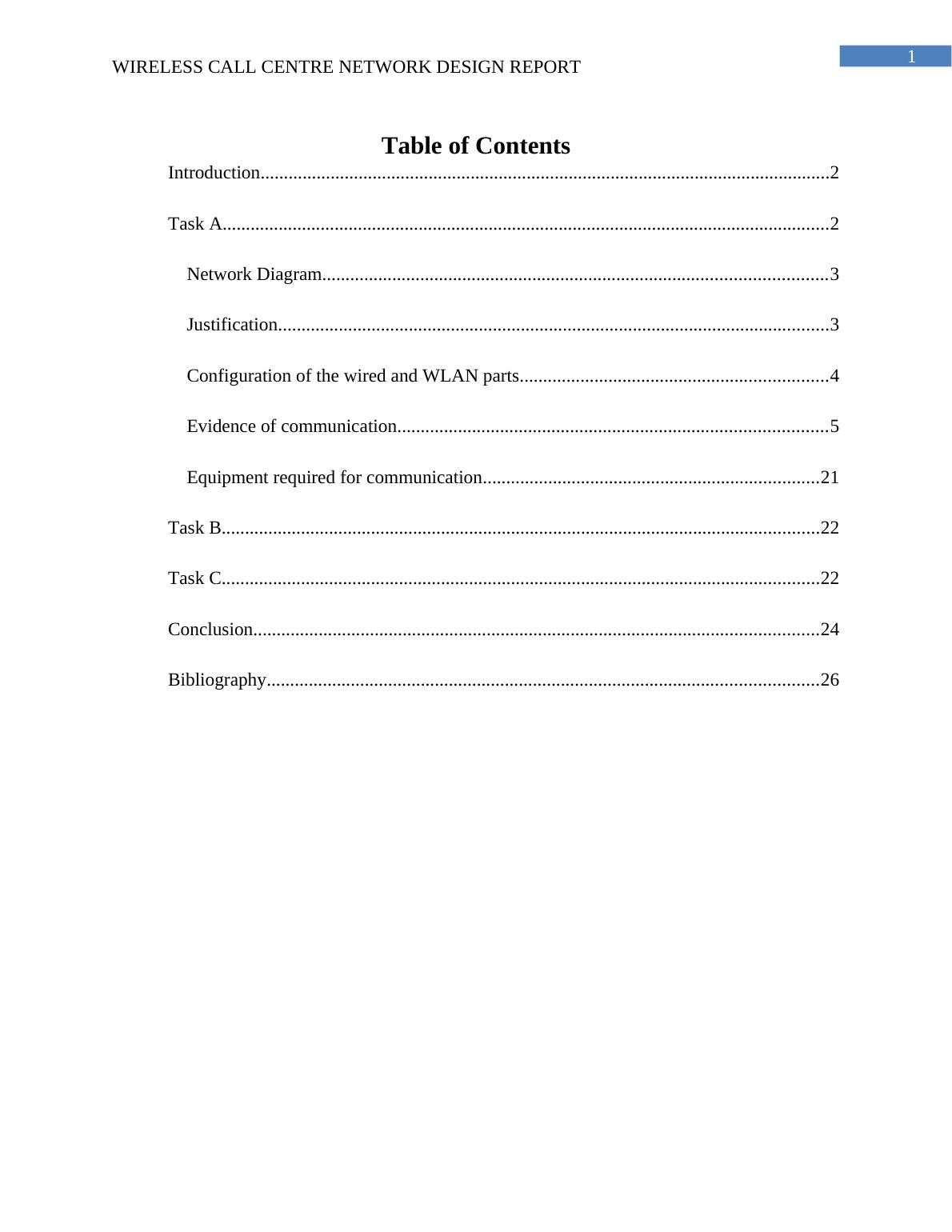
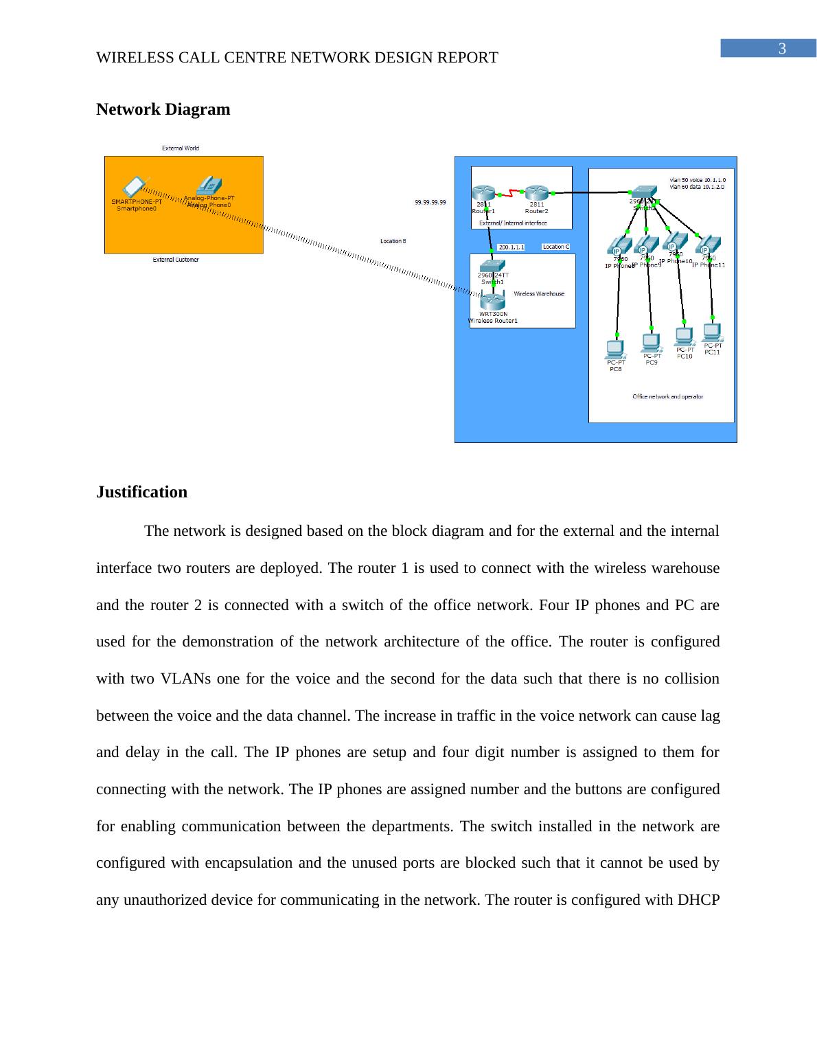
WIRELESS CALL CENTRE NETWORK DESIGN REPORT 27 27 WIRELESS CALL CENTRE NETWORK DESIGN REPORT Wireless Call Centre Network Design Report Name of the Student Name of the University Author’s Note Introduction 2 Task A 2 Network Diagram 3 Justification 3 Configuration of the wired and WLAN parts 4 Evidence of communication 5 Equipment required for communication 21 Task B 22 Task C 22 Conclusion 24 Bibliography 26 Introduction The report is prepared for company ABC for the development of the wireless call center network design. Evidence of the use of routing protocol

Wireless Call Centre Network Design Report Name of the University Author's Note

   Added on 2021-04-21

ShareRelated Documents
Running head: WIRELESS CALL CENTRE NETWORK DESIGN REPORTWireless Call Centre Network Design ReportName of the StudentName of the UniversityAuthor’s Note
Wireless Call Centre Network Design Report Name of the University Author's Note_1
1WIRELESS CALL CENTRE NETWORK DESIGN REPORT Table of ContentsIntroduction..........................................................................................................................2Task A..................................................................................................................................2Network Diagram............................................................................................................3Justification......................................................................................................................3Configuration of the wired and WLAN parts..................................................................4Evidence of communication............................................................................................5Equipment required for communication........................................................................21Task B................................................................................................................................22Task C................................................................................................................................22Conclusion.........................................................................................................................24Bibliography......................................................................................................................26
Wireless Call Centre Network Design Report Name of the University Author's Note_2
2WIRELESS CALL CENTRE NETWORK DESIGN REPORT IntroductionThe report is prepared for company ABC for the development of the wireless call centernetwork design. The network is designed following the requirement and improvement of thesecurity of the voice and the data communications. The initial plan of the network is followed forthe development of the network and enabling communication between the warehouse and theexternal customer. The network solution is created in cisco packet tracer and the devices areconfigured for testing the functionality of the network. The commands used for configuration ofthe IP phone and the router are attached in the document such that network administrator canfind it easy to configure the hardware device installed in the company’s site. The errors in theconfiguration are tested multiple times and the installation location of the routers and the accesspoints are verified for increasing the security of the network. The network diagram is labelledwith the IP address used for configuring the interface and a justification of the design is given inthe document.Task A
Wireless Call Centre Network Design Report Name of the University Author's Note_3
3WIRELESS CALL CENTRE NETWORK DESIGN REPORT Network DiagramJustificationThe network is designed based on the block diagram and for the external and the internalinterface two routers are deployed. The router 1 is used to connect with the wireless warehouseand the router 2 is connected with a switch of the office network. Four IP phones and PC areused for the demonstration of the network architecture of the office. The router is configuredwith two VLANs one for the voice and the second for the data such that there is no collisionbetween the voice and the data channel. The increase in traffic in the voice network can cause lagand delay in the call. The IP phones are setup and four digit number is assigned to them forconnecting with the network. The IP phones are assigned number and the buttons are configuredfor enabling communication between the departments. The switch installed in the network areconfigured with encapsulation and the unused ports are blocked such that it cannot be used byany unauthorized device for communicating in the network. The router is configured with DHCP
Wireless Call Centre Network Design Report Name of the University Author's Note_4
4WIRELESS CALL CENTRE NETWORK DESIGN REPORT with the range of IP address for the different VLANS and the device connected in the networkand automatically assigned with the IP address for enabling the communication. Explanation of the use of routing protocolRouting protocol is required for connecting the interfaces of the router 1 and router 2 andenabling the devices connected at the end of the interface to communicate with the deviceinstalled at the other interface of the second router. The routers are configured with EIGRPbecause it consumes less resource and reduces the load on the network. If there is a change in thetopology of the network it can be revised using the new next hop address (Loo, Mauri and Ortiz2016). Different vlans are created for the data and the voice network and the switch is configuredwith the encapsulation and switch port mode access for allowing the device to use the VLAN forcommunication (Lo Mills 2016). The default VLAN is used by the trunk port unless the VLANis not defined and thus it is important to allow the access of the VLAN to the range of the switchport such that the data is communicated using the VLAN created for communication of the voiceand the data. Configuration of the wired and WLAN partsA wireless router is used and connected with the switch for connecting the wirelessdevices in the network. A proper network cabling plan is followed for connecting the routers andthe switches in the network. The IP address used for configuring the devices are used for labelingthe devices in the network diagram. The use of the trunk protocol helps in optimizing theperformance of the access ports and it decreases the time for packet forwarding (Kizza 2017).The packet are received on the port with the VLAN value added on the header for forwarding itto the destination address. A point to point link is established between the devices connected inthe network for allowing the different vlans to communicate with each other. The IEEE 802.1 Q
Wireless Call Centre Network Design Report Name of the University Author's Note_5
5WIRELESS CALL CENTRE NETWORK DESIGN REPORT encapsulation is also used for the insertion of the tag about the VLAN and identify the frame andthe packet (Yan and Yu 2015). The encapsulation of the trunk also helps in transmission of thedata packets in the end to end traffic through the network utilizing the same VLAN. During the configuration of the port using the access mode the VLAN that would be usedfor carrying the traffic to that interface needs to be specified. If the VLAN is not defined in theaccess mode the default VLAN i.e. VLAN 1 is used for carrying the data traffic (Rautaray andAgrawal 2015). A new VLAN can be created in the switch and allowed its access unless if theaccess port receives the data packet with 802.1Q tag embedded in the header the without learningthe VLAN information the packet is dropped. Evidence of communicationFor providing the evidence of the communication between the devices used forconfiguration of the network the following screenshot is attached. For testing the VOIPconnection a call is placed from the IP phone with the assigned phone number and if the call issuccessfully established then the VOIP connection is also tested.
Wireless Call Centre Network Design Report Name of the University Author's Note_6

End of preview

Want to access all the pages? Upload your documents or become a member.

Related Documents
Warehouse Network Set Up and Configuration
|28
|1798
|183

Network Infrastructure and Configuration Report 2022
|18
|2381
|22

Network requirement analysis and plan
|20
|2452
|94

Project for a Small Company | Als Pty Ltd
|14
|1411
|160

Network Security and Infrastructure Setup Report 2022
|19
|2423
|25

BN321 - Advanced Network Design
|17
|1750
|35